
Datasheet


SYSKONP500, P800, P1500, P3000 and P4500
Computer Controlled Laboratory Power Supply
2 GMC-I Messtechnik GmbH
Applications Range
Konstanters are suitable for use wherever electronic modules with
controlled direct voltage or controlled current need to be supplied
with electrical power, especially in the fields of R&D, testing,
production, test systems and training.
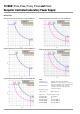
Due to their characteristic U-I-P curve, the devices have a broad
range of operation, making it possible to cover a large range of
applications with a single device.
Due to their short response times, SYSKON KONSTANTERs can
be used for replication and simulation of onboard electrical sys-
tems, for example in automotive applications. Test signals speci-
fied in the corresponding standards can be generated. The fact
that these voltage-current-time profiles can be saved to memory
at the Konstanter for running independent sequences is highly
advantageous. When used in test systems, it is thus possible to
significantly reduce workload for the control computer. Further
functions for test applications of this sort include the Min-Max
function for acquiring extreme values and the tolerance band
function which generates a signal when measured values do not
lie within the specified tolerance limits.
The Konstanter thus serves as an autonomous test system for
many applications.
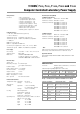
Adjustable Functions (selection)
– Voltage and current setpoint values
– Voltage and current limit values (soft-limits)
– Activate / deactivate the output
– Overvoltage protection trigger value (OVP)
– Overcurrent protection trigger value (OCP)
– Delay time for reaction to overvoltage
– Selection of the desired reaction when OVP and OCP
are triggered
– Delay time for reaction to overcurrent
– Performance after power on
– Reset device settings
– Save device settings
– Recall device settings, individually or sequentially
– Function selection for trigger inputs
– Function selection for signal outputs
– Configurable status and events management
with enabling windows (via computer interface)
– Activate / deactivate digital displays
Retrievable Information (selection)
– Presently measured voltage and current values
– Minimum and maximum measured voltage and current values
– Current output power
– Current device settings
– Current device status (i.e. control mode, overtemperature etc.)
– Occurred events (i.e. mains failure, overtemperature,
overvoltage, overload etc.)
– Device ID (via computer interface)
Protection and Additional Functions
– Sensor terminals protected against polarity reversal
and automatic switching to auto-sensing
– Protection against excessive temperature
– Output protected against reverse polarity
– Front panel control disabling
– Backup battery for device settings memory
– Recognition of mains or phase failure
– Inrush current limiting
Performance After Power on
In the event of mains failure, it’s important to specify which
operating state the device will assume when power is restored.
This may be extremely important if the device is used in long-term
testing applications.
One of the following states can be selected:
– Reset = default setting (0 V, 0 A, output deactivated)
– Standby = last used configuration but with deactivated output
– Recall =
last used configuration – same as when the instrument
was last switched off, with
active output if it was active prior to
mains failure
– Recall a device configuration from setup memory
Set Output Voltage and Output Current
Output voltage and output current can also be adjusted using the
rotary encoders or the numeric keypad if desired. The rotary
encoders are used exclusively for adjusting voltage and current.
The decimal place to be changed is selected with the scroll keys.
Additional functions and parameters can be accessed and
adjusted with the keys.
Switching the Output On and Off
The power output can be switched on and off by pressing the
appropriate key, with a computer command or by applying a
signal to the trigger input. When switched off, the output is highly
resistive and will not be galvanically isolated from the power con-
sumer. The on/off status is indicated by the LED on the key.
Protection and Additional Functions
A multitude of protection and additional functions have been
integrated, for example:
• Limiting of the setting ranges for voltage and current
• Overvoltage protection (OVP) with adjustable response delay
and reaction
• Overcurrent protection (OCP) with adjustable response delay
and reaction
• Protection in the event of reversed polarity at the sensing leads
• Automatic switching to auto-sensing
• Protection against excessive temperature
• Output protected against reverse polarity
• Front panel control disabling
• Backup battery for device settings memory
• Mains failure detection
• Inrush current limiting
• Line voltage monitoring
Line voltage monitoring
To protect the device, the power output is deactivated in the
event of line undervoltage. The device must be restarted with
„Power ON“.
Dynamic Sink
A dynamic sink is activated by the control loops as required for
rapid discharging of the output capacitors.
This allows for short response times when switching to smaller
setpoint values. Depending upon the application, the sink
function can also be disabled.