
Datasheet


GMC-I Messtechnik GmbH 3
SYSKONP500, P800, P1500, P3000 and P4500
Computer Controlled Laboratory Power Supply
Auto-Sensing
The device can be switched to sensing mode operation (remote
sensing) in order to compensate for voltage drop at the output
leads. Sensing lead terminals are available to this end at the
analog interface. If the (–) negative sensing terminal is connected
to the negative load point, the device is automatically switched to
sensing mode operation. Maximum compensatable voltage drop
is 1 V per output lead.
Front Panel Control Disabling
The controls can be disabled to prevent unauthorized operation
by pressing the appropriate key, with a computer command or by
applying a signal to the trigger input.
Analog Control Inputs
Voltage and current can also be adjusted by via the control inputs
at the analog interface. A 5 V signal corresponds to 100% of the
respective nominal value.
These inputs can be switched on and off using the keys, or with
computer commands.
The controlled output quantity is the sum of the digital setpoint
value and the specified value at the control input.
This function makes it possible to superimpose these control
signals onto the output quantities.
Monitor Outputs
The actual values for output voltage and current can be
acquired at the monitor outputs as a standardized signal (10 V
corresponds to 100% nominal value).
Trigger Inputs
Two floating trigger inputs are available for controlling device
functions. The following trigger input assignments can be
selected:
– output = Switch the power output on and off
– local lock = Disable controls
–SQS = (sequence step) Step-by-step control of a
stored sequence
– sequence = Start / stop the sequence function
(arbitrary function)
–
Analog input
= Activate / deactivate the analog control inputs
Signal Outputs
Programmable Control Outputs
The analog interface is equipped with three digital control outputs
for status messages to external monitoring devices, for switching
external components on and off, or for coupling purposes.
The status of these outputs can be defined either directly, or
depending upon the following device statuses:
– Output on or off
– Voltage or current regulation
– Sequence function (arbitrary function) running or finished
– SSET signal status for the sequence function (arbitrary func-
tion)
– Limit value message for the measuring function (tolerance
band)
Min-Max Measured Value Memory
The Min-Max function automatically acquires and saves minimum
and maximum voltage and current values.
Tolerance Band (in combination with Min-Max function)
Measured output values can be continuously compared with
stored upper and lower tolerance band values. Evaluation is
possible via the programmable control outputs.
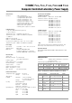
Memory
The memory function makes it possible to save and recall device
configurations using a battery-backed memory module.
The memory module is equipped with two storage areas:
• Setup memory:
15
memory locations for complete
configurations
• Sequence memory: 1700 memory locations for the following
sequence parameters:
– voltage setpoint USET,
– current setpoint ISET,
– dwell time TSET
– function request FSET
with the ability to invoke subsequences
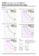
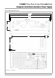
Sample Application
Generation of a characteristic voltage curve in an automotive elec-
trical system when starting the engine
Note:
The drop times can be influenced by the input impedance of the
DUT.
Balancing Function (adjust)
Offset and final values for setting and measured values for output
quantities voltage and current are balanced digitally in the device.
The user can execute balancing as required with this function.
DAkkS Calibration Certificate
All SYSKON Konstanters are shipped with a DAkkS calibration
certificate (DAkkS = German Akkreditation Body) issued by our
DAkkS test laboratory.
Operating Software for Computer Controlled Systems
Convenient software in English for quick and easy use of the SYS-
KON KONSTANTER is available free of charge. Its central element
is the Soft Front Panel. This makes it possible for the user to take
targeted advantage of the comprehensive range of included func-
tions within his own application – without any programming at all.
The panel has a clear-cut layout and is broken down into taskspe-
cific displays.
The software detects KONSTANTERs which are connected to the
various possible interfaces including USB, RS 232 and GPIB.
KONSTANTERs detected by the software are identified automati-
cally and can be selected for the respective application.
If several KONSTANTERs are connected, the software can be
started separately for each device, and each device can be indi-
vidually controlled.
U [V]
12
6
4.5
5
t [ms]
15 5 2000 10