Operating Instructions SECUTESTBASE(10) / PRO und SECULIFE STBASE(25) Test Instruments for Measuring the Electrical Safety of Devices per VDE 0701-0702, IEC 62353 and IEC 60974-4 3-349-752-03 16/9.
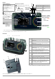
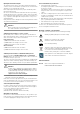
Display of symbols for devices connected to the USB master interface (see below) – For keyboard * – For barcode/RFID scanner * – For printer – For USB drive ® test probe Controls Display of special symbols: – Measurement at IT system active – Offset for RPE active ! Lightning symbol: mains to test socket White identified and fused high current path Probe Type SK2-25A (Z746C) Test current 200 mA / 25 A Kink protection grommet max.
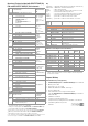
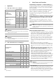
Measuring Function Test Current/Voltage Single measurements, rotary switch level: green Protective conductor resistance RPE RPE RISO UISO Test current (200 mA) SECUTEST BASE10/PRO, SECULIFE ST BASE: 10 A 1 (feature G01) and SECULIFE ST BASE 25: 25 A 1 (feature G02) Insulation resistance (PC I/PC II) Test voltage IPE IPE~ IPE= ULN Protective conductor current, RMS AC component DC component Test voltage IB IB~ IB= ULN Touch current, RMS AC component DC component Test voltage IG IG~ IG= ULN Dev
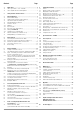
Contents Page Page 1 Applications ..................................................................... 5 8 Single Measurements .................................................... 25 1.1 1.2 Table: Types of DUTs – Tests – Standards .....................................5 Table: Single Measurements and Regulations .................................5 2 Safety Features and Precautions ..................................... 5 8.1 8.2 8.3 8.4 8.5 8.6 8.7 8.7.1 8.7.2 8.7.3 8.7.4 8.7.5 8.8 8.9 8.10 8.
2 1 Applications 1.1 Table: Types of DUTs – Tests – Standards SECUTEST BASE(10), SECUTEST PRO and SECULIFE ST BASE(25) test instruments fulfill the requirements of the applicable EU guidelines and national regulations. We confirm this with the CE mark. The relevant declaration of conformity can be obtained from GMC-I Messtechnik GmbH.
Opening the Instrument / Repairs The test instrument may not be used: The instrument may only be opened by authorized, trained personnel in order to ensure flawless operation and to assure that the guarantee is not rendered null and void. Even original replacement parts may only be installed by authorized, trained personnel.
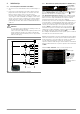
3 General Operation 3.1 Measured Value Display The following items appear at the display panel: • The selected measuring function or standard • Measured values with abbreviations and units of measure • Setting parameters, i.e. type of connection and measurement type • Symbols for softkey operation • Wiring diagrams, notes regarding the test sequence and error messages Green progress bars appear in the header for single measurements, and orange progress bars appear for test sequences.
3.5.3 Report Tapes from Thermal Printers Report tapes can be printed out with the Z721S thermal printer (accessory: Z722S thermal paper). As from firmware V2.1.0: Adjustments of the test report and import of a company logo (only applicable for thermal printer Z721S) can now be directly performed in the SETUP of the test instrument, see page 14. Note Code Recognition Please make sure that the printed codes are recognized by your scanner.
4 Initial Start-Up 4.1 Connecting the Test Instrument to the Mains 4.1.1 ➭ See section 12 for nominal mains values (nominal ranges of use). ➭ Connect the test instrument to the mains cable via its inlet plug and insert the mains plug into an electrical outlet. The function selector switch can be set to any position.
4.1.2 Automatic Recognition of Mains Connection Errors 4.2 The device automatically recognizes mains connection errors if the conditions in the following table have been fulfilled. The user is informed of the type of error, and all measuring functions are disabled in the event of danger. Insert the double plug from test probe P1 or P2 into socket 1 or 2 respectively such that the plug with the white ring makes contact with the socket with the vertical bar.
4.3 Device Settings SETUP For the purpose of initial start-up, we recommend setting the following basic parameters in the order shown at the right: Setup 2/3 > Culture > Language (for user interface) Setup 2/3 > Culture > Keyboard Layout (for alphanumeric entries) Setup 1/3 > System > Date / Time (for reports generating) Setup 1/3 > System > Brightness (display brightness as %) Setup 1/3 > Auto.
Setup 2/3 > Culture Manual selection for language and keyboard layout Page 2/2: Info on date format, decimal separator Select language for user interface Select language for user interface PRINT ESC HELP Country-specific keyboard layout for USB or touch-screen keyboard MEM Info: date format, decimal separator * Jump back to next higher menu level Setup 1/3 > System 1/2 PRINT Menu selection for date, volume and brightness To parameter for default values ESC Date and time setting menu (see settings
Database Functions Setup 1/3 PRINT ESC HELP MEM Database 1/2 Menu selection for database functions, page 1 of 2 Display additional menu pages PRINT ESC Delete database content (but not its structure) Caution: Data are irretrievably deleted! HELP Display database MEM Only with inserted USB drive: backup database to USB flash drive (FAT32 formatted) Only with inserted USB drive: restore database from USB flash drive Database 2/2 Menu selection for database functions, page 2 of 2 Display additional
Printer Functions – Selection and Settings for Thermal Printer as an Example Setup 2/3 > Printer Selection of connected printer PRINT ESC Printer Z721S: Printer info/printer settings HELP Printer Z721D*: Printer info/printer settings * Phase-out model Printer Z721E*: Barcode label printer Printer info/printer settings MEM * for test instrument firmware as from 1.8.
5 Internal database 5.1 Creating Test Structures, General A complete test structure with data regarding customers, properties, buildings, floors, rooms and test objects can be created in the test instrument. This structure makes it possible to assign single measurements or test sequences to test objects belonging to various customers. Manual single measurements can be grouped together into a so-called “manual sequence”.
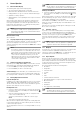
Test Structure – Hierarchy of Object Levels in the SECUTEST BASE(10) Database Customer ID Zip code Designation City Street address Device 1/4 2/4 3/4 4/4 Id Test interval* Comment Cost center* Department* Designation Type Serial number Location Manufacturer Safety class Manual sequence ID Designation Measurement 1 Measurement 2 Measurement 3 * Test interval: additionally available for test instruments with database extension SECUTEST DB+ (Z853R) and/or feature KB01or SECUTEST DB comfort
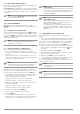
Test Structure Customer View – Hierarchy of Object Levels in the SECUTEST PRO and SECULIFE ST BASE(25) or in Devices with Database Extension Z853R or Feature KB01 MEM Customer Database Customer Id Designation Street Zip code City Device ME Device** Customer Manual Sequence 1/6 2/6 3/6 4/6 Id Test interval* Comment No. appl. part Cost center type B** 5/6 6/6 Designation Type Serial No. No. appl. part Cepartment type BF** Location Manufacturer Safety classs No. appl.
5.
5.
5.4.1 General Procedure for Creating Test Structures After selection with the MEM key, all setting options for the creation of a tree structure are made available on three menu pages (1/3, 2/3 and 3/3). The tree structure consists of structure elements, referred to below as objects. Results of measurements/tests cannot be saved but under the structural elements of type „Device“ or „ME device“ – these are also referred to as „test object“ in the following.
5.4.2 Searching for Structure Elements 5.4.4 Deleting the Database ➭ Scroll to the first menu page (MEM 1/3) with the help of the key. ➭ Scroll to the third menu page (MEM 3/3) with the help of the key. ➭ Press the text symbol in order to search for text. ➭ Press the ID symbol in order to search for an ID number.
6 Connecting the Device Under Test ➭ Connect the DUT in accordance with the schematic diagrams included in the online help function.
6.5 Special Conditions • Note Protection Class II Devices with Protection Class I Mains Plugs If the device under test is equipped with a protection class I plug although it complies with protection class II, protection class I is recognized by the test instrument. If this is the case, switch the protection class parameter from I to II.
7 Notes on Saving Single Measurements and Test Sequences At the end of each test, test results can be saved under an ID number which is unequivocally assigned to the respective test object (= device or ME device). Depending on the initial situation, i.e.
8 Single Measurements 8.1 • • • • • • General The desired measurement is selected with the help of the green pointer on the rotary switch and the green semicircle. The respective measurement is configured with the help of the softkeys. The parameter settings can be accessed by pressing the softkey with the symbol shown at the right. The measurement type parameter displayed in each case in the footer can be changed directly using the key shown at the right without having to exit the measuring view.
8.2 Meaning of Symbols in the User Interface 8.
Note Measurements and measurement series can only be saved after measurement has been completed. Measured values can only be added to intermediate buffer memory during a measurement. Customer, location and other entries cannot be changed in the memory menu. These have to be selected directly in the database and entered or changed.
Protection Class I Devices Special Case: Line Voltage at Test Socket (for testing PRCDs) – Measurement type PE(TS) - P1 (active) – DUT mains plug to test socket – Test probe P1 to P1 terminals Schematic Diagram Measurement via current clamp sensor at permanently installed DUT – Measurement type PE(mains) - P1 clamp – Test probe P1 to P1 terminals – Clamp to COM-V (only withSECUTEST PRO or feautureI01 with optional WZ12C current clamp sensor) Schematic Diagram Protective conductor resistanc
Wiring Diagram Entering and Deleting Offset Values The test instrument determines protective conductor resistance by means of a 4-pole measurement.
Test Sequence with Connection to the Test Socket ➭ Set the rotary switch to the RPE position. ➭ Select measurement type or connection type, and test current. After pressing the Ip key, you have direct access to the test current parameters: each time this key is pressed, the setpoint value shown in the measuring window is switched to the next value. ➭ Connect the DUT to the test socket. ➭ Start the test: press the START/STOP key.
8.
Protection Class I Devices with Outputs for Safety Extra-Low Voltage and Exposed Conductive Parts – Measurement type LN(TS) - P1 – DUT mains plug to test socket – Test probe P1 to P1 terminals Wiring Diagram Schematic Diagram Special Case: Permanently Installed Protection Class I Devices – Measurement type PE(mains) - P1 – Test probe P1 to P1 terminals Insulation resistance is measured successively between short-circuited mains terminals (L-N) and the safety extra-low voltage outputs which can
Protection Class I Devices with Terminals for Applied Parts – Measurement type PE(TS) - P1 – DUT mains plug to test socket – Test probe P1 to P1 terminals Protection Class I Devices with Exposed Conductive Parts – Measurement type LN(TS) - P1//PE(TS) – DUT mains plug to test socket – Test probe P1 to P1 terminals Schematic Diagram Schematic Diagram Insulation resistance is measured between protective conductor terminal PE and external, short-circuited applied parts which can be contacted
Attention! Prerequisite for Testing The measurement of insulation resistance may not be conducted on protection class I devices which have not passed the protective conductor resistance test. Note The insulation test cannot be performed for all DUTs, for example electronic devices, EDP equipment, medical devices etc. Leakage current measurements must be performed for these DUTs (see Section 8.7). Observe the notes in the service instructions.
Protective Conductor Current Measuring Method (direct measurement) 8.7.1 Protective Conductor Current – IPE The device under test is operated with mains power. Current which flows through the PE conductor to earth at the mains side of the device connection is measured.
Wiring Diagram Wiring Diagram (AT3-I I I E probe to COM-V ) Alternative Measuring Method (equivalent leakage current) – Alternative measurement type – DUT mains plug (protection classes I) to test socket Measurement of protective conductor current via current clamp sensor with voltage output for permanently installed DUTs (only with SECUTEST PRO or feature I01 with optional WZ12C current clamp sensor) – Clamp measurement type Schematic Diagram Schematic Diagram After activating test voltage, leak
Setting Measuring Parameters for IPE Measuring Meaning Parameter Measurement Type, Direct Direct measuring method Differential Differential current measurement Equivalent leakage current method Alternative AT3 adapter Clamp Test Sequence for Direct Measuring Method Suitable for DUT Connection via Test socket, AT16DI/AT32DI (direct or diff.
Test Sequence with Differential Current Method ➭ Prior to all leakage current measurements, please make sure that the measurement parameters „Ref. voltage L-PE“ and „Testingfreq. Alt“ have been correctly set in the SETUP, see section 6.2. ➭ Set the rotary switch to the IPE position. ➭ Select the Differential measurement type: – By setting the parameters or – Directly by pressing the key shown at the right ➭ Connect the DUT’s mains plug (protection class I) to the test instrument’s test socket.
8.7.
Alternative Measuring Method (equivalent leakage current) – Alternative measurement type P1 – DUT mains plug to test socket – Test probe P1 to P1 terminals Alternative measuring method with 2-pole measurement (P1–P2) – Alternative measurement type P1 - P2 – Test probe P1 to P1 terminals – Test probe P2 to P2 terminals Schematic Diagram Schematic Diagram After activating test voltage, leakage current is measured between short-circuited mains conductors L and N (DUT mains plug) and accessible c
Direct Selection – Setting Polarity – for Direct and Differential Only Measuring Meaning Parameter Measurement Type, L/N or N/L Selection of polarity for mains voltage to the test socket Prerequisites for Touch Current Measurement • • • Visual inspection has been passed. For protection class I devices: protective conductor resistance testing has been passed. Insulation resistance testing has been passed.
contacted with test probe P1. If the DUT includes terminals for applied parts, they must be short-circuited and contacted with test probe P1 as well. 8.7.
Alternative Measuring Method (equivalent leakage current) – Alternative Measurement Type (P1) – DUT mains plug connected to the test socket – Test probe P1 to P1 terminals Schematic Diagram, Protection Class I Measurement Method with Current Clamp Sensor for Permanently Installed DUTs – Clamp measurement type – Clamp to COM-V (only withSECUTEST PRO or feautureI01 with optional WZ12C current clamp sensor) Schematic Diagram After activating test voltage, leakage current is mea
Setting Measuring Parameters for IG Measuring Meaning Parameter Measurement Type Test Sequence Suitable for DUT Connection via Test socket, AT16DI/AT32DI (only diff.
8.7.4 Leakage Current from the Applied Part – IA Alternative Measuring Method (equivalent patient leakage current) – Alternative Measurement Type P1 – DUT mains plug (PC1) connected to test socket – Probe to P1 Terminal IA Switch Position Single measurements, rotary switch level: green MeasureMeasureMeasuring Functions ment Type, ment Type, With Mains Without to Test Mains Socket to Test Socket Direct P1 IA Alternative P1 Perm. con.
Setting Measuring Parameters for IA 8.7.5 Patient Leakage Current – IP Measuring Meaning Parameter Measurement Type, Direct P1 Alternative P1 Perm. con.
Direct Measuring Method – Permanent connection measurement type P1 – Permanent connection – Probe to P1 terminal Setting Measuring Parameters for IP Measuring Meaning Parameter Measurement Type Schematic Diagram Direct P1 Perm. con.
8.8 Probe Voltage – U Wiring Diagram U Switch Position Single measurements, rotary switch level: green MeasureMeasureMeasuring Functions ment Type, ment Type, With Mains Without to Test Mains Socket to Test Socket PE - P1 U PE - P1 (with mains) U U~ U= U U~ U= Probe voltage, RMS Alt. voltage component Direct voltage component Probe voltage, RMS Alt. voltage component Direct voltage component Direct, alternating and pulsating voltages of up to 253 V can be measured.
8.9 Measuring Voltage – U (with SECUTEST PRO or feature I01 only) Wiring Diagram U Switch Position Single measurements, rotary switch level: green MeasureMeasureMeasuring Functions ment Type, ment Type, With Mains Without to Test Mains Socket to Test Socket V – COM U V - COM (with mains) U U~ U= U U~ U= Measuring voltage, RMS Alt. voltage component Direct voltage component Measuring voltage, RMS Alt.
8.10 Measuring Time to Trip for RCDs of the Type PRCD – tA Test Sequence ➭ Set the rotary switch to the tA position. ➭ Plug the PRCD into the test socket at the test instrument and connect the test probe to P1. tA ➭ Start the test: press the START/STOP key. ➭ Acknowledge the warning which indicates that line voltage will be connected to the test socket.
8.11 Function Test – P P The device under test can be subjected to a function test with mains voltage via the integrated test socket. The test socket is tested for short-circuiting before switching to line voltage (a statement resulting from the short-circuit test can only be made regarding the DUT itself when a single-phase DUT is being tested).
8.
Setting Measuring Parameters Measuring Parameter Connection Type Meaning EL1 adapter Measurement with EL1 adapter and DUT at test socket for single-phase extension cords Measurement with AT3-I I I E adapter for single and 3-phase extension cords Measurement with VL2E adapter for single and 3-phase extension cords AT3-I I I E adapter VL2E adapter See corresponding single measurements for the testing of RPE and RISO. Note Test Sequence with VL2E Adapter ➭ Set the rotary switch to the EL1 position.
9 Special Functions – EXTRA Measurement with Temperature Sensor Depending on the device configuration, either the QR code for the Internet link to the operating instructions or the measuring view for the temperature measurement is displayed. EXTRA SECUTEST BASE(10) EXTRA Temperature measurement functions with either a Pt100 or a Pt1000 temperature sensor – the sensor type is automatically detected internally.
Test Sequence with Current Clamp Sensor Measurement with Current Clamp Sensor EXTRA A current clamp measurement is possible in this case, independent of measuring functions RPE, IPE or IG, e. g. for measuring current at permanently installed devices. Schematic Diagram ➭ ➭ ➭ ➭ Set the rotary switch to position EXTRA. Select measuring function IZ. Set the clamp factor at the current clamp sensor. Clamp Factor: Set the clamp factor at the test instrument and at the current clamp sensor.
10 Test Sequences Status Upon Shipment (default settings) Automated test sequences, rotary switch level: orange Switch Standard/ Measure- ConnecSetting Test sequence ment Type tion Preconfigured (freely adjustable) test sequences VDE 0701-0702 Passive Test socket A1 Type Protec- Freely Configurable Sequence depending on the selected configuration tion class (protection class, type of application part) SK I + SK I I** SK I + SK I I** SK I + SK I I** SK I + SK I I** SK I + SK I I** A2 VDE 0701-0702 Act
Sequence Designer With the help of Sequence Designer software (up to firmware 1.8.3), test sequences can be created at the PC and transferred to the test instrument via a USB connection or a USB flash drive.
Meaning of Symbols in the User Interface – Test Sequence Sym- Softkey Variants, Test Sequence bol Test for Protection Class I Devices Exposed, conductive parts are connected to the protective conductor so that they are not charged with voltage if the basic insulation should fail. Test for Protection Class II Devices These devices are equipped with double insulation or reinforced insulation. Test for Protection Class III Devices These devices are supplied with safety extra-low voltage (SELV).
Change Classification Parameters Conveniently (Option Feature E01 (Touch Screen)) Classification Parameter – VDE 0701-0702-IT Parameter 1/2 Setting Options / Meaning Standard/Test Sequence VDE 0701-0702, see table above VDE 0701-0702-IT Protection class 1 Connection 1 2 ➭ Per touch click (brief tapping) on the respective window of the classification parameters the corresponing selection menu opens. ➭ You automatically go back to the start menu by selecting the desired parameter. 2 2/2 Meas.
Classification Parameter – VDE 0701-0702-PRCD Parameter 1/2 Setting Options / Meaning Standard/Test Sequence VDE 0701-0702, see table above VDE 0701-0702-IT, see table above VDE 0701-0702-ExtC, see previous table Classification Parameter – IEC 62353 Parameter 1/2 Setting Options / Meaning Standard/Test Sequence VDE 0701-0702, see table above VDE 0701-0702-IT, see table above VDE 0701-0702-ExtC, see table above VDE 0701-0702-PRCD, see previous table VDE 0701-0702-PRCD 2 Protection class 1 Connection
Classification Parameter – IEC 60974-4 Parameter 1/2 Setting Options / Meaning Standard/Test Sequence VDE 0701-0702, see table above VDE 0701-0702-IT, see table above VDE 0701-0702-ExtC, see table above VDE 0701-0702-PRCD, see table above IEC 62353, see previous table IEC 60974-4 Protection class 1 Connection type1 Class I, Class II or Class I+II test socket Perman. connect. Adapter: AT16/32-DI-Adap.
❑ Set measurement duration of individual test steps (as of firmware 1.5.0) Testing time for the respective measurement can be influenced with these parameters. If a test step for a single measurement is involved, the entire test step has a duration of the time entered in seconds. If a test step for a multiple measurement is involved, the measurement duration for each measuring point is influenced. If 0 seconds is selected, continuous measurement is conducted which can only be ended by pressing a key.
10.3 Connecting the DUT 10.6 ➭ Connect the DUT to the test instrument in accordance with the selected test sequence. – Test socket – Permanent connection – Adapter Executing and Evaluating Test Steps Manual Evaluation of Visual Inspection (prerequisite: “visual inspection” sequence parameter is preset to “on”.
Test Steps with Automatic Evaluation (RISO, IPE) 10.8 Ending the Test Sequence “Sequence finished” appears at the display. Initial Display (memory screen) The measured value is ascertained automatically within a specified period of time. The evaluation cycle is visualized as follows: the progress bar starts at the left-hand edge of the display and moves to the right. When it reaches the rightmost position, evaluation has been completed. The test sequence is then automatically resumed.
11 Warnings, Error Messages and Notes Error messages or notes regarding the individual tests or test sequences are displayed as popups. Differentiation is made amongst 5 types of messages: • • • • • Fatal error Error Warning Note – INFO Question Warning Warnings indicate hazards which, if not avoided, may result in severe injury. Single test: Warnings have to be acknowledged or cleared by pressing the OK key, before the test or the test sequence can be resumed.
11.1 List of error messages Error Messages Possible Causes Corrective Measures Mains Connection Errors – ➭ Please remove the SECUTEST’s Protective conductor PE at the mains outlet at which the SECUTmains plug from this outlet and arEST is being operated is conductrange to have the outlet/installaing voltage! This detection function tion inspected by a qualified electrician without delay. Do not makes use of the metallized START/STOP key on the test operate any other devices at this instrument.
Error Messages Possible Causes Corrective Measures – Momentary line voltage at the ➭ The 10 A/25 A-RPE measurement SECUTEST test instrument is outis only available when line voltage side of the range permitted for a is between 220 V and 240 V or 10 A/25 A-RPE measurement (110 110 V and 120 V at 50 Hz or 60 Hz. to 120 V or 220 to 240 V).
Error Messages Possible Causes – – 68 Corrective Measures A device under test is connected to ➭ If the device under test normally the SECUTEST and has been generates a leakage current of started up, whose leakage current greater than 10 mA (e.g. large (measured by means of the differheaters), temporarily increase the ential current method) exceeds the “residual current protection” value limit value specified in setup. selected in setup to 30 mA and try again.
Error Messages Possible Causes – – Corrective Measures ➭ Determine whether or not the device under test is defective. ➭ In the case of DUTs which are intended for operation at an outlet that’s protected with a 16 A fuse, a short-circuit may be detected under certain circumstances if, for example, they include a PTC resistor (e.g. large floodlights). Be sure to use a 3-phase test adapter in order to test devices of this sort (e.g. the AT3-IIIE).
Error Messages Database Processing Error Possible Causes – One of the fields was filled in with ➭ Please be certain to complete all invalid content while processing an mandatory fields (identified in red). existing database object. ➭ If necessary, check your entries to the fields for invalid special characters. – The ID field was not filled in while creating a new device. ➭ Fill in the ID field. – There’s already an object with the same ID under the “Customer” database object.
Error Messages Possible Causes Corrective Measures Error while creating database backup file on USB flash drive Make sure that a minimum storage capacity of 100 MB is available on the USB drive and/or delete any data files no longer required. ➭ If the problem persists, save the data of the USB drive on another storage device and format the USB drive (file system FAT32).
Error Messages Printer Connection Error Possible Causes Corrective Measures – – The printer is not connected. An incompatible printer has been connected. ➭ Connect the printer to the USB port before pressing the PRINT key. ➭ Make sure that the utilized printer is listed in section 14.1, “List of Suitable Printers with USB connection”. – No recording chart in the thermal printer. The printer is defective. ➭ Insert a new recording chart.
Error Messages GMC-I Messtechnik GmbH Possible Causes Corrective Measures – Amount of data exceeded for Micro QR code in the ID to be printed. ➭ Abbreviate the ID or select another output type (QR code, DataMatrix, Aztec, Code128, Code39, EAN13) in the Setup. – The length of the ID has been exceeded and is too long for printing by micro QR Code.
11.
This page has been left blank intentionally.
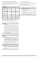
12 Function Test at Test Socket Tests, 62638 (DIN VDE 0701-0702) / IEC 62 353 (VDE 0751) Function tA PRCD Characteristic Values Display Range / ResoNominal Range of lution Use Measured Quantity Protective conductor resistance RPE Insulation resistance 9 RISo Leakage current alternative measurement 2 IPE, IB, IG, IA Leakage current direct measurement 3 IPE, IB, IG, IA, IP Leakage current differential current measurement 4 IPE, IB, IG Line voltage UL–N 10 Load current IL 1 999 m 1 m 1.00 … 9.
Function Measured Quantity Current via current clamp sensor 1 mV : 1 mA] (V–COM sockets 6 7) Display Range / ResoNominal Range of lution Use 1 ... 99 mA 0.1 ... 0.99 A 1.0 ... 9.9 A 10 ... 300 A 0.1 ... 9.9 mA Current via current clamp sensor [10 mV : 1 mA] (V–COM sockets 6 7) 10 ... 99 mA 0.10 ... 0.99 A 1.0 ... 30.0 A IClamp 0.01 ... 0.99 mA Current via current clamp sensor [100 mV : 1 mA] (V–COM sockets 6 7) 1.0 ... 9.9 mA 10 ... 99 mA 0.10 ... 3.00 A 1 ...
Reference Ranges Line voltage 230 V AC 0.2% Line frequency 50 Hz 2 Hz Waveform Sine (deviation between effective and rectified value < 0.5 %) Ambient temperature + 23 C 2 K Relative humidity 40 60% Load resistance Linear Nominal Ranges of Use Nominal line voltage Nom. line frequency Line voltage waveform Temperature 100 V 240 V AC 50 Hz ... 400 Hz Sinusoidal 0 C + 40 C Ambient Conditions Storage temperature Relative humidity Elevation Deployment – 20 C + 60 C Max.
13 Maintenance 13.1 Housing Maintenance 13.4 No special maintenance is required for the housing. Keep outside surfaces clean. Use a slightly dampened cloth for cleaning. Avoid the use of cleansers, abrasives or solvents. 13.2 Testing the Color Display and the Buzzer (self-test parameter) The color display can be tested for failure of individual segments and loss of color components on page 3/3 of the setup menu in the SETUP switch position under the self-test parameter.
This must be taken into consideration during technical safety inspections or, instead of the insulation resistance measurement, the protective conductor current measurement must result in a value of less than 3.5 mA (or less than 7 mA if the equivalent leakage current method is used). There are also 4 accessible conductive parts on the SECUTEST..., at which the touch current measurement must result in a value of less than 0.
14.2 • • List of Suitable Barcode Scanners and RFID Scanners with USB connection Z751A barcode scanner Z751E RFID scanner (programmer) 14.3 Application of USB Storage Devices For various device functions (see section 3.5.5 and 5.2) USB flash drives must be directly connected to the test instrument. The connected USB storage medium must fulfill at least the following requirements in order to be applied with your test instrument: • The file system on the USB flash drive is formatted for FAT (FAT32).
14.4 Bluetooth Interface (SECUTEST PRO BT (comfort) or Feature M01) The Bluetooth® interface is designed for the use of push-print function, see section 10.8.
14.6 Index Numerisch 2nd Test Probe ...................................................................2, 23 2-Pole Measurement (P1-P2) .................................................. 23 Measuring Sequences Standard Selection .......................................................... 57 Measuring Uncertainty ............................................................ 57 Multiprint ..................................................................................
15 Repair and Replacement Parts Service Calibration Center* and Rental Instrument Service If required please contact: GMC-I Service GmbH Service Center Beuthener Straße 41 90471 Nuremberg, Germany Phone: +49-911-817718-0 Fax: +49-911-817718-253 e-mail: service@gossenmetrawatt.com www.gmci-service.com 16 Product Support If required please contact: GMC-I Messtechnik GmbH Product Support Hotline Phone: +49-911-8602-0 Fax: +49 911 8602-709 e-mail support@gossenmetrawatt.
GMC-I Messtechnik GmbH 85
Edited in Germany • Subject to change without notice • PDF version available on the Internet GMC-I Messtechnik GmbH Südwestpark 15 90449 Nürnberg, Germany Phone: +49-911-8602-111 Fax: +49 911 8602-777 e-mail: info@gossenmetrawatt.com www.gossenmetrawatt.