
User Manual

GMC-I Messtechnik GmbH 3
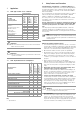
Overview of Features Included with SECUTEST BASE(10),
PRO and SECULIFE ST BASE(25) Test Instruments
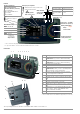
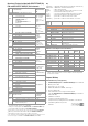
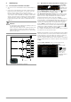
Switch
Position
Measuring Function
Test Current/Voltage
Measurement
Type, Connection
Type
Single measurements, rotary switch level: green
R
PE
Section
8.5
R
PE
Protective conductor resistance
PE(TS) - P1 passive
PE(TS) - P1 active
PE(mains) - P1
PE(mains) - P1 clamp
2
P1–P2
3
I
P
Test current (200 mA)
SECUTEST BASE10/PRO,
SECULIFE ST BASE: 10 A
1
(feature G01)
and SECULIFE ST BASE 25: 25 A
1
(feature G02)
RISO
Section
8.6
R
ISO
Insulation resistance (PC I/PC II) LN(TS) - PE(TS)
LN(TS) - P1
P1–P2
3
PE(mains) - P1
PE(TS) - P1
LN(TS) - P1//PE(TS)
U
ISO
Test voltage
IPE
Section
8.7.1
I
PE
Protective conductor current, RMS Direct
Differential
Alternative
AT3-Adapter
2
Clamp
2
I
PE~
AC component
I
PE=
DC component
U
LN
Test voltage
IB
Section
8.7.2
I
B
Touch current, RMS Direct
Differential
Alternative (P1)
Perm. connection
Alternative (P1–P2)
I
B~
AC component
I
B=
DC component
U
LN
Test voltage
IG
Section
8.7.3
I
G
Device leakage current, RMS Direct
Differential
Alternative
AT3-Adapter
2
Clamp
2
I
G~
AC component
I
G=
DC component
U
LN
Test voltage
IA
Section
8.7.4
I
A
Leakage current from the applied part, RMS
Direct (P1)
Alternative (P1)
Perm. con. (P1)
U
A
Test voltage
IP
Section
8.7.5
I
P
Patient leakage current, RMS
Direct (P1)
Perm. con. (P1)
I
P~
AC component
I
P=
DC component
U
LN
Test voltage
U
Section
8.9
U
Probe voltage, RMS
P1–P2
P1–P2 (with mains*)
* Polarity param.
U
~
Alternating voltage component
U
=
Direct voltage component
U
Measuring voltage, RMS
2
V – COM
V – COM (with mains)
U
~
Alternating voltage component
2
U
=
Direct voltage component
2
ta
4
Section
8.10
ta
PRCD time to trip for 30 mA PRCDs
U
LN
Line voltage at the test socket
P
Section
8.11
Function test at the test socket
Polarity parameter
I Curr
ent between L and N
U V
oltage between L and N
f F
requency
P Active power
S Appar
ent power
PF Power factor
Probe Measuring Functions
EL1
Section
8.12
Extension cord with adapter: continuity, short-circuit,
polarity (wire reversal)
EL1 adapter
AT3-IIIE adapter
VL2E adapter
EXTRA
Section 9
Reserved for expansion during the course of software updates
°C/°F Temperature measurement
2
with Pt100 / Pt1000
V – COM
IZ Current clamp measurement
2)
with current clamp sensor
V – COM
1
10 A/25 A R
PE
measurements are only possible with line voltages of
115/230 V and line frequencies of 50/60 Hz.
2
Voltage measuring inputs with SECUTEST PRO and SECULIFE ST BASE only
(or instrument with feature I01) and SECULIFE ST BASE(25)
3
Connection for 2
nd
test probe for 2-pole measurement with SECUTEST
PRO only (or instrument with feature
H01) and SECULIFE ST BASE(25)
4
Measurement of time to trip is not possible in IT systems.
5
No checking for reversed polarity takes place when the EL1 adapter is used.
6)
Connection type not available for
SECULIFE ST BASE 25
(feature G02)
Key
Alternative = alternative measurement (eq. leakage current meas.)
Differential = differential current measurement
Direct = direct measurement
LN(TS) = short-circuited L and N conduct
ors at test socket
P1 = measurement with test probe P1
P1-P2 = 2-pole measurement with test probes P1 and P2
PE-P1 = measurement between PE and test probe P1
PE(TS) = protective conductor at the test socket
PE(mains) = protective conduct
or at the mains connection
Switch
Position
Standard Measurement Type, Connection Type
Automated test sequences, rotary switch level: orange
Preconfigured (freely adjustable) test sequences – default settings
A1
VDE 0701-0702
Passive measurement type, test socket
A2
VDE 0701-0702
Active measurement type, test socket
A3
VDE 0701-0702-EDV
Parametrization for EDP (active)
A4
IEC 62353
(VDE 0751)
Active measurement type
A5
IEC 62353
(VDE 0751)
Active measurement type
A6
IEC 60974-4
Connection type: test socket
A7
IEC 60974-4
Connection type: AT16-DI/AT32-DI
A8
VDE 0701-0702
Extension cord measurement type
(RPE, RISO), adapter:
EL1
/VL2E/
AT3-I I I E
AUTO
VDE 0701-0702
Active measurement type, test socket
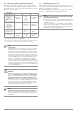
Differences with Regard to Included Features
SECUTEST... Feature BASE PRO PRO BT
comfort
—
SECULIFE... — ST BASE —
ST BASE 25
Touch screen/keyboard
E01
10 A RPE test current
G01
25 A RPE test current
G02
2
nd
test probe
H01
Voltage meas. inputs*
I01
SECUTEST DB+
KB01
SECUTEST DB comfort
KD01
Bluetooth
®
M01
Antimicrobial housing
— ST BASE
* For voltage measurement or for connecting a current clamp sensor for
clamp current measurement, or an AT3 adapter, and for temperature
measurement via RTD
Scope of Delivery
Standard Version (country-specific)
1 SECUTEST BASE(10)/PRO or SECULIFE ST BASE(25) test instrument
1 Mains power cable
1Test probe, 2 m, not coiled
1 USB cable, USB A to USB B, 1.0 m long
1 Plug-on alligator clip
1 KS17-ONE cable set for voltage measuring input
(only with
SECUTEST PRO
and
SECULIFE ST BASE(25)
or instrument
with feature I01)
1 Calibration certificate
1 Condensed operating instructions
–
Comprehensive operating instructions available on the Internet
1 Card with registration key for the
Software