Operating Instructions SSP-KONSTANTER 32 N Series SSP 120, SSP 240 and SSP 320 Programmable Power Supplies 3-349-267-03 11/5.
GMC-I Messtechnik GmbH
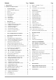
Contents Page Contents I Initial Inspection . . . . . . . . . . . . . . . . . . . . . . . . . . . . . . . . . .4 II Warnings and Safety Precautions . . . . . . . . . . . . . . . . . . . . .4 Page 4.14 INCR <> and DECR <> Keys . . . . . . . . . . . . . . . . . . . .47 4.15 Device RESET . . . . . . . . . . . . . . . . . . . . . . . . . . . . . . . . .47 4.16 Selecting Remote and Local Control Modes . . . . . . . . . . . . . . . . . 47 1 Technical Description . . . . . . . . . . . . . . . . . . .
I Initial Inspection Immediately after receipt, unpack the KONSTANTER and all included accessories, and inspect for damage and completeness. Unpacking Great care must be exercised when removing the electronic device from the package. ☞ Pull the KONSTANTER from its package. ☞ In doing so, do not grasp rotary knobs, terminals or jacks in order to avoid damage. ☞ Do not allow the KONSTANTER to fall out of the packaging. Controls, displays, terminals and internal components might otherwise be damaged.
1 Technical Description 1.1 Features and Range of Applications 1.2 Functions Depending upon where they are used and prevailing local conditions, electrical and electronic devices may be subject to significant supply power fluctuation in the absence of stabilizing and back-up systems. Automotive electrical system voltage characteristics during starter motor operation offer a typical example.
1.3 Options and Accessories 1.4 Functional Principle Options Power Supply Required DC supply power is generated for each respective circuit from mains power which has been fed to the power pack via an interference suppression filter, a wire fuse, the mains switch and inrush current limiting. (See order information on last page.) Devices can be equipped with an IEEE 488 plug-in interface module for integration of SSP KONSTANTERs into IEC bus controlled systems.
Setup Procedure Setup data are processed and forwarded to the respective I/O controller of the respective function unit. Each setting value for output voltage, output current or overvoltage protection triggering is converted to a proportional control voltage by a 12 bit DAC, and is fed to the respective controller or comparator as a setpoint or a reference quantity.
1.5 Technical Data Analog Interface Connection 11-pole plug-in screw terminal block Reference potential Output minus pole, floating TRG input Connector pin assignments: 1.5.1 General Data Power Supply Connection Input: Output: 10 A IEC inlet plug 10 A IEC inlet socket, without switch, without fuse 230 V ~ +10 -15%, 47 to 63 Hz See chapter 1.4.3 Max. 50 AS 1 ea. T 4 A / 250 V (6.3 x 32 mm, UL) internal: 1 ea.
Electrical Safety Safety class Overvoltage category Fouling factor Earth leakage current I II for mains input I for output and interfaces 2 2.5 mA, typ. IEC 61010-1:1990 + A1:1992 / DIN EN 61010-1: 1993 / VDE 0411-1:1994 DIN VDE 0160:1988 + A1:1989 class W1 EN 60950:1992 / VDE 0805:1990 Protection Electrical isolation Mains/output–PE Mains–output IP 20 for housing per IEC 529:1989, EN 60529:1991, VDE 0470-1:1992 Test voltage 1.35 kV~ 2.7 kV~ (type test: 3.
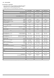
1.5.3 Electrical Data Electrical Data for 120 W Models Unless otherwise specified, all entries are maximum values and apply within an operating temperature range of 0 to 50C, within the nominal power range and the nominal line voltage range of 230 V 10% after a warm-up period of 30 minutes. Percentages make reference to the respective setting value or measured value.
Electrical Data for 240 and 320 W Models 1) Unless otherwise specified, all entries are maximum values and apply within an operating temperature range of 0 to 50C, within the nominal power range and the nominal line voltage range of 230 V 10 % after a warm-up period of 30 minutes. Percentages make reference to the respective setting value or measured value. SSP 240-20 SSP 240-40 SSP 240-80 SSP 320-32 32 N 20 RU 20 P 32 N 40 RU 12 P 32 N 80 RU 6 P 32 N 32 RU 18 P 0 ... 32 V 0 ... 20 V 0 ..
2 Initial Start-Up 2.1.2 Installation to 19'' Device Racks The SSP KONSTANTER housing allows for use as a benchtop instrument, as well as for installation to a 19'' rack. One KONSTANTER and a cover plate, or two devices next to each other can be installed to the rack. The benchtop instrument can be quickly retrofitted for rack mounting. 2.1 Preparing for Operation 2.1.
➃ Unscrew the feet from the bottom of the housing. Remove the rubber inserts from the feet to this end. The screws are then exposed. ➄ If you would like to electrically connect the two KONSTANTERs, use the “mains jumper cable” and “RS 232 bus cable” accessories. ➅ Install the two devices to the rack.
Data Queries COM1/COM2 RS 232 IN SSP PC/Controller 9-pin Socket Connector 9-pin Plug TxD_IN 2 2 RxD RxD_IN 3 3 TxD GND_IN 5 5 GND RS 232 IN RS 232 OUT SSP SSP 9-pin Plug RxD_OUT 9-pin Socket Connector 2 2 TxD_IN TxD_OUT 3 3 RxD_IN GND_OUT 5 GND_IN 5 Figure 2.1.6 a Pin Assignments for 9-Pin Plug and Socket Connectors The serial interface furnished with this KONSTANTER series is addressable. Up to 30 KONSTANTERs can be addressed via this interface.
Abbreviated Power-Up Test In order to shorten power-up time, or if problems occur with the normal power-up test, an abbreviated power-up test can be used: With the device switched off, press and hold the key. Turn the mains switch on. Release the key after approximately 1 second. If this procedure is used, only essential initialization steps are run during power-up.
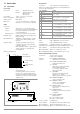
3 Controls, Display Elements and Terminals Note: Numbers in brackets make reference to the figures included below. 1 2 4 [1] 3 5 6 8 7 Mains Switch For turning the KONSTANTER on and off After switching the KONSTANTER on, a self-test is performed with a duration of approximately 8 seconds. After successful completion of the self-test, the KONSTANTER briefly displays its interface address and the version number of the installed firmware, one after the other.
☞ ☞ During auto-sensing: Sensing lead polarity is reversed, or an output lead is/was interrupted or was not taken into consideration when adjusting OVSET, so that the voltage at the output terminals which is relevant for the OVP function is increased by the amount to be compensated for at both leads, and is higher than USET voltage as controlled by the sensors at the load side (too little difference between selected USET and OVSET values).
Additional KONSTANTER functions can be selected with the
[21] Analog Interface The output interface offers two options: Take constant voltage or constant current from the terminal strip at the rear panel of the KONSTANTER. The analog interface facilitates the following functions: Remote adjustment of output voltage and current with analog control voltages ranging from 0 to 5 V, or 5 to 0 V ☞ Connect sensing leads for compensation of voltage drops in the output leads chapter 5.8 / chapter 5.
4 Manual Operation and Device Functions Initializing the Procedure ☞ Slightly turn (1) the Uset knob [7]. ! The display is switched from Uout (measured voltage value) 4.
! Iset – Output Current Each time the key is pressed, output voltage is changed by an amount which corresponds to the value selected with the resolution setting function. Pressing and holding the respective key results in rapid scrolling, regardless of the step width. The procedure for selecting output current Iset is identical to the procedure for selecting output voltage Uset (4.1.2).
If the Pon RCL function is active, the output is automatically reactivated after the device has returned to its normal operating temperature. Functions which may influence the status of the output include: Functions Meaning OVP (OVSEt) Overvoltage protection Overcurrent protection OCP Pon (POWER_ON) SEq Sequence trG (T_MODE) Manual Operation page 25 Remote Operation page 69 page 26 page 68 page 26 page 69 chapter 4.7.4 page 28 page 70 page 74 4.
dLY – Output Off Delay for OCP 4.7 Operating Menu via the FUNCTION Key Functions The FUNCTION menu consists of the following functions for configuring the KONSTANTER’s parameters: • Function group Function Parameter (numeric / text) Ulim Ilim OVP OCP dLY Pon NP: xx.xx NP: xx.xx NP: xxx.x TP: oFF / on NP: xx.xx TP: rSt / SbY / rcL Settings UI- TP: oFF / on / rSt See description on page 26.
Settings • ☞ Repeatedly press the key or ☞ Press the key [14] at the front of the KONSTANTER. If no settings have yet been changed via the FUNCTION menu after switching the device on, the SEt function group is accessed upon pressing the key. Forward scrolling through function groups in this menu: ☞ Press and hold the key and repeatedly press the <> key at the same time.
4.7.1 SET – “Setup” Function Group Ulim – Upper Voltage Setting Limit FUNCTION Functions Press once See functions description on page 22. ENTER Settings Jump to last edited setup function FUNCTION + Press repeatedly if necessary Cursor position Resolution of numeric parameter The procedure is described in principle in chapter 4.7. ! The Ulim display appears in the window for the setup function, * along with a related numeric parameter [V].
OCP – Overcurrent Protection Pon – Specifying a Power-On Status Functions Functions See functions description on page 22. • Setting Parameter Setting Parameters: ☞ OFF: OCP function is inactive ☞ rSt: (RESET) Factory default settings are utilized Continuous current limiting (current regulation) Use automatic KONSTANTER configuration after power on.
UI_ – U/I Min-Max Measured Value Memory (MINMAX) rnd – Rounding Off the Displayed Measured Value Functions Functions • • • • • • • • • • • • Save minimum and maximum measured voltage and current values. Reads out stored values for Umin, Umax, Imin and Imax at the display, or via the computer interface. The MINMAX function can be temporarily set to OFF, for example before deactivating the output when changing devices under test.
4.7.2 AnIF – “Analog Interface” Function Group The analog interface allows for remote control of the KONSTANTER. An isolated digital control input (TRG IN+ / TRG IN-) and digital signal outputs (SIG1 / SIG2) are available in addition to analog setting options. Other devices can be controlled in this way (e.g. counters, alarms, SSP KONSTANTERs and many more). A master-slave system can be set up in combination with a second or several SSP KONSTANTERs (see also chapter 5).
Setting SiG1 – Signal Output 1 ☞ Procedure for selecting Sig1: see also chapter 4.7, “Settings”. Functions • • • • • • Digital open collector output with reference to AGND, max. switching voltage min. 30 V DC, max. switching current min. 20 mA (e.g. ext. load shedding relay). Indicates the status of the power output. If an event occurs which is associated with the selected parameter, a corresponding signal is generated at the output.
4.7.3 SEq – The Sequence Function Group Responses to Sequence Start and Stop • Description Test sequences can be generated with the SEQUENCE function group (in accordance with DIN if desired). Setpoints are specified for voltage (Uset) and for current (Iset), as well as for the associated time intervals (tset) to this end. In addition, a signal for external processing can be specified for each test step (Sset). . Tset1 Tset2 15 U/V Tset3 2000 • • • 20 12 • 6 4,5 • t/ms Figure 4.7.
tSEt – Memory Location-Specific Dwell Time SSEt – Setting a Digital Switching Function Functions Functions Special dwell time (see also Figure 4.7.3 a): • For the voltage-current value pair at a specific memory location within a SEQUENCE • For all status signals generated for these memory locations • • • Setting Range 00.00 s The tdEF value is used. 00.01 s to 99.99 s Maximum resolution: 0.01 s 99.
tdEF – Dwell Time Independent of Memory Location Strt – Sequence Start Address Functions Functions • • • Default dwell time: – For all voltage-current value pairs included in a sequence to whose memory locations no special dwell time has been assigned (tSEt = 00.00) – For all status signals generated for these memory locations tdEF is used primarily to speed up programming if the value for a certain dwell time is used repeatedly within a given SEQUENCE. • • • • Setting Range • 0.01 s to 99.
StoP – Sequence Stop Address rEP – Sequence Repetitions Functions Functions • • • • • • • • ! The end of a range within which memory locations or content will be deleted or added The SEQUENCE is always defined by means of a start address and a stop address. Memory location at which a SEQUENCE will be ended The stop address can correspond to any memory location from 11 to 255. The stop address is selected immediately before initially starting a new SEQUENCE.
! SEq – Sequence, Automatic Memory Recall Functions • The first valid memory location is now executed, and the values saved to this location (Uset, Iset and SSEt) are read out to the power output and the signal output. The LOCKED/SEQ LED blinks slowly . LOCKED/SEQ Controls automatic and step-by-step sequence runs. Setting Parameter ☞ Strt: select step-by-step control , jump to start address (status: RDY HOLD), execute command with the key.
Setting all Required Values for a Sequence FUNCTION Read the detailed explanations included in chapter 4.6 and 4.7.3 first. 1 Press the . key. 2 The function groups or functions menu appears. 1 Function Groups Menu 2 Functions Menu 3 If the functions menu is not displayed, press the key in order to return to the function groups menu.
Execute Next Address (status: HOLD HOLD) Checking the Sequence Functions Functions ! The following parameters can be checked at the display menu while the sequence is running, or when it has been suspended: > Pout = max. output power > U_ = min. output voltage = max. output voltage >U > I_ = min. output current >I = max.
Stop Sequence at Current Address (status: RUN HOLD) End the Sequence at the Stop Address (status: HOLD RDY) Functions Functions ! ! • • • A running SEQUENCE can be suspended for an indefinite period of time. Uset, Iset and Sset retain the values specified in the current memory location. Selected dwell time Tset of the current memory location is not taken into consideration. The output retains its switching status (output On or Off).
Executing the Start Address and Beginning Step-by-Step Control (status: HOLD HOLD or RUN HOLD) SEQUENCE in run status LOCKED/SEQ Functions ! ENTER SEQUENCE in hold status LOCKED/SEQ CE/LOCAL ENTER FUNCTION End at FUNCTION Select: Resume sequence Restart sequence Sequence is resumed ! current address • • Procedure: ☞ ?With interrupted or running SEQUENCE, – press the key and then browse with the <> key, the <> or the key until SEq start appears and execute the comman
! The buS functions menu appears. ☞ Select the Addr function by pressing the key, or the and simultaneously the <> key or the <> key. ! ☞ Procedure for selecting bAud and setting the desired parameter (see chapter 4.7): ! Addr appears at the left-hand display, and the last selected parameter appears at the right-hand display.
SbIt – Selecting the Number of Stop Bits • ! Either 1 or 2 stop bits can be used. Settings at the SSP KONSTANTER and the controller must be identical. Settings ☞ Procedure for selecting Sbit and setting the desired parameter Switching the 7-segment display from Uout and Iout to the following measured values: Pout xxx.x Max. output power U_ xx.xx Min. output voltage xx.xx Max. output voltage U I_ x.xxx Min. output current x.xxx Max. output current I • (see chapter 4.
Display of Data Stored to Sequence Memory (11 ... 255) Upon Execution of Settings After executing the command, selecting a memory location (<> or <> key) and pressing the key, the device is switched to the read-out mode. Values saved to sequence memory blink at the display.
4.9.3 Clearing the Contents of a Defined Memory Range ! Functions • All data are deleted from memory locations from the current start address to the current stop address. clr dAtA and start stop blink alternately at the display in order to identify the range to be deleted. ☞ Acknowledge by pressing the key. ! The range of memory locations from the start address to the Settings ☞ Press the key. ! ☞ Select memory location 0 (clr) with the <> key or the <> key.
4.9.4 Inserting a Memory Location Settings The start and stop addresses define the working range for the command described below. Memory locations which do not lie within this range are protected against access when the command is executed. Each time a memory location is inserted, the content of the previous stop address is lost. ☞ Select a start address and a stop address with the help of the Functions sequence submenu. ☞ Press the key.
4.9.5 Deleting a Memory Location Attention: Currently selected start and stop addresses and start and stop addresses saved to setup memory are not corrected automatically! The start and stop addresses define the working range for the command described below. Memory locations which do not lie within this range are protected against access when the command is executed. Each time a memory location is deleted, an empty memory location is inserted at the stop address.
! Sto and the last selected address appear at the display. ☞ Select the desired address with the <> key or the <> key. 4.9.6 Deleting the Contents of a Memory Location Functions • • ☞ Press the The contents of any desired individual memory location from address 11 through 255 can be deleted. This has no effect on other memory addresses. and keys simultaneously. ! A c (for clear) appears in the right-hand display next to the selected memory location address number.
4.10.2 Recall from SEQUENCE Memory Addresses 11 to 255: Uset, Iset, tSEt and SSEt values for the sequence function ! Data from memory locations 11 through 255 can be recalled at any time during programming. ☞ Press the key. ! rcl appears at the left-hand display, and the last selected memory location number appears at the right-hand display. ☞ Select the desired address (11 ... 255) by pressing the <> key or the <> key. ☞ Acknowledge your selection with the key.
Function Selection ☞ key: Abort function selection, return to function group selection. Text Parameters ☞ key Abort selection, switch to display of selected text parameter. Sequence Control ☞ key Abort a suspended sequence or step-by-step control at the current memory location. 4.14 INCR <> and DECR <> Keys The increment and decrement keys execute various functions depending upon settings.
5 Analog Interface U-MON (output) Analog voltage output signal, proportional to output voltage Uout acquired by the sensing leads. 5.1 Connector Pin Assignments (0 ... 10 V SIG1 OUT, SIG2 OUT (output) Digital status signal outputs with reference to AGND SIG1 OUT indicates the status defined by SIG1 txt. SIG2 OUT indicates the status defined by SIG2 txt. Signal type Open collector Max. switching voltage 30 V DC Max. switching current 20 mA ☞ For a detailed description refer to chapter 5.3.
5.2 Auto-Sensing Mode In order to be able to take advantage of highly constant output voltage at the power consumer even if long leads are used, sensing leads can be used to compensate for voltage drops within the output leads. Functions Sensing lead terminals +SENSE and –SENSE Acquirement of output voltage, which decisively influences the voltage measuring and control circuits, directly at the power consumer (instead of at the output terminals).
5.4 Regulating Output Voltage 5.5 Regulating Output Current Functions Functions Output voltage Uout can be set by means of an external control voltage Usu via control inputs Uset+ (non-inverting) and Uset (inverting). Output current Iout can be set with an external voltage Usi via the control input Iset+. The following applies in the constant voltage regulating mode: Uout = USET + Usu ksu USET = selected voltage setpoint ksu = voltage control coefficient = Uoutnom / 5 V Max.
5.6 Voltage Monitoring Output 5.7 Current Monitoring Output Functions Functions The U-MON terminal reads out a voltage UMU with reference to AGND, which is proportional to output voltage Uout. The I-MON terminal reads out a voltage UMI with reference to AGND, which is proportional to output current Iout. U-MON serves as a control voltage for master-slave series connection (see chapter 5.10.2). I-MON serves as a control voltage for master-slave parallel connection (see chapter 5.9.2).
5.8 Trigger Input 5.9 Parallel Connection Functions If output current from a single KONSTANTER is insufficient for the respective application, the outputs of any number of KONSTANTERs can be parallel connected. The TRG IN floating optocoupler input allows for remote control of a device function using a binary signal. The function to be controlled is selected with the T-MODE setting (in the trG display). ☞ A detailed description is included on page 28 and page 74.
This procedure is continued until load current triggers current regulating at the output with the lowest voltage setting when the setpoint value for cumulative current is reached. This output maintains constant load current until the load resistor is short-circuited. UA / V Uout1 Uout2 Ideal working range for voltage regulation at the load Uout3 RL Ideal working range for current regulation at the load RL IA / A Iout1 Figure 5.9.
Check output current at the slave device displays. 5.9.2 Master-Slave Parallel Connection Functions As opposed to direct parallel connection, master-slave parallel connection offers significant advantages: Equally suitable for voltage and current regulation Output current at each of the slaves can be precisely matched to master output current by adjusting Rsym. Changes appear immediately at the respective display. Undo short-circuiting of the load.
5.10 Series Connection Functional Principle If output voltage from a single KONSTANTER is insufficient, or if you want to generate a voltage, the outputs of several KONSTANTERs can be connected in series. Warning! Maximum allowable cumulative voltage for series connection is 120 V (or 240 V with grounded neutral point). 5.10.1 Direct Series Connection ! The sum of all individual output voltages is made available to the power consumer.
Switch slave 1 on and configure: 5.10.2 Master-Slave Series Connection trG out Functions As opposed to direct series connection, master-slave series connection offers significant advantages: Equally suitable for voltage and current regulation Output parameters (cumulative output voltage, current limiting, output on/off) are set entirely by the master device. All interconnected KONSTANTERs are equally loaded.
5.11 Varying the Internal Output Resistance Value Connection Connect the analog interface as shown in Figure 5.11 b. Functions In the voltage regulating mode, internal output resistance has a value of close to 0 . The internal output resistance value can be increased for certain applications, for example simulation of long output cables or weak automotive batteries. The selected (open-circuit) output voltage is reduced in proportion to increasing load (Figure 5.11 a).
6 Operating Commands Nearly all of the device functions offered by the SSP KONSTANTER can be remote controlled via the IEEE 488 interface (= IEC 625), or the RS 232C interface. Example 2: The following abbreviations can be used for the DELAY? query command: Device settings and device responses are triggered by character strings, which are transmitted in ASCII code. The only exceptions to this rule are several IEC bus-specific functions.
Stringing Commands Together You can string several commands together and transmit them as a single unit. In this case, the individual commands are separated with semicolons (;). Blanks can be entered to the left and to the right of the semicolons. Example: USET 10; OUTPUT ON; IOUT? Comments The individual commands are executed in the order they were received. Setting and query commands can be mixed in a single command string.
6.
6.4 Description All setting, query, register management and interface commands are listed alphabetically in the following pages (*A..., *B..., *C..., ..., A..., B..., C..., ...). In addition to the application-specific overview in the previous chapter, setting, query and status commands are included in the appendix arranged according to function. register, and bit 3 (DDTE, define device trigger error) would be set in event register B.
*LRN? – Complete Configuration Query (LEARN) Functions Complete list of all configurable functions. Complete list of all current parameter settings. After completion of the command, a signal is transmitted to the controller. The message can be read out via the serial and the parallel interface.
Note Memory locations 11 through 253 can be recalled by means of interface programming, even if the sequence has not been opened. If an invalid (empty) memory location is accessed in sequence memory, command execution is aborted. Err 21 appears at the display, and bit 5 is set in event register B (SEQE, SEQuence error). If a USET or ISET parameter exceeds the ULIM or ILIM limit value during recall, Err 21 appears at the display and bit 5 is set in event register B (SEQE, SEQuence error).
SRQ is also reset. *WAI – Wait to Continue *TRG – Device Trigger Function Functions Triggering of functions specified with *DDT (see also page 61) Functions The *WAI command is of no significance for programming the KONSTANTER. It serves to synchronize the interface protocol in accordance with the IEC 488.2 standard. Programming Setting command: *TRG Example (HP Basic): OUTPUT 713;"*TRG" Note If DDT memory is empty, the trigger function is considered undefined.
Example (HP Basic): DCL, SDC – Device Clear Function Functions Clears input and output buffers at the computer interfaces. e.g. requested data which have not been picked up Clears internal interface waiting times or disabling. TheKONSTANTER is ready to receive data. Manual operation is not possible.
– Is changed from TRUE to FALSE (input ). The registers are reset as a result of querying. The *CLS setting command clears all event registers. Example – Incorrect programming command occurs. – Command error bit 5, CME, is set to 1 in the ESR. – Bit 5 remains set, even in the event of subsequent correct commands. – After querying ESR, the CME bit is reset.
Example (HP Basic): ILIM, ILIM? Current Setting Limit Value Settings Display: Function and manual operation: See explanation on page 25. OUTPUT 713; "IMAX?" ENTER 713; A$ DISP A$ IMAX +02.8550 IMIN? – Minimum Measured Current Value Programming Setting command: ILIM v Parameter: v (value) Parameter type: Real number Setting range: 0 v ILIMmax Function and manual operation: See explanation in chapter 4.8.1. Programming Query command: IMAX? Device Type Nom. current [A] ILIMmax [A] 2 2.0 3 3.
Default setting: If necessary, the numeric value is rounded off once again for the 4-place digital display. 0.00 [A] (after RESET, *RST) Example (HP BASIC): Display: MODE? – Querying the Momentary Control Mode OUTPUT 713;"ISET 11.3" {current setpoint: 11.3 A} Comment ISET may not be set to a value of greater than ILIM. Any setting command to this effect is not executed. Bit 1 would otherwise be set in event register B (limit error), and bit 4 in the standard event register (execution error).
Example (HP Basic): OUTPUT, OUTPUT? – Activate / Deactivate the Output Function and manual operation: See explanation in chapter 3 [3]. Display: OUTPUT 713; "OVSET?" ENTER 713; A$ DISP A$ OVSET +035.
REPETITION, REPETITION? – Number of Repetitions for SEQUENCE Function Function and manual operation: See explanation on page 33. Programming Setting command: REPETITION n Parameter: n (number) Parameter type: Integer Setting range 0 continuous repetition Format: Default setting: 1 to 255 sequence repetitions nnn unchanged (after RESET, *RST) Example (HP Basic): OUTPUT 713;"REPETITION 100" {100 repetitions} Query Display the number of sequence repetitions.
SIG1_SIG2, SIG1_SIG2? – Analog Interface Signal Outputs SRQ – SERVICE REQUEST Function and manual operation: As opposed to manual operation, the computer generated SIG1_SIG2 command addresses both signal outputs simultaneously. Functions Signal output 1: dependent upon power output status. Signal output 2: dependent upon current output control mode. The status of the SIG1_SIG2 function is not saved as a device setting with the SAVE key.
Comments We recommend enabling the following events at the corresponding registers for an SRQ message: Execution Error START_STOP, START_STOP? – Memory Location Start and Stop Addresses for the SEQUENCE Function CME Command Error EXE QYE Query Error OTPA OTP Activated TSTE Self-Test Error LIME Limit Error Function and manual operation: As opposed to manual operation, start and stop memory addresses are entered to a command.
Programming STORE, STORE? – Transferring Parameters Directly to Memory Functions The STORE command and its parameters can only be queried via an interface with appropriate programming. It immediately overwrites all values of the memory location with the new parameter data. Memory location contents are not shifted. Command Value Range Meaning a Store? Query contents of a memory range from the start address to the stop address (AAA and EEE) b Store? n n = 11 ...
TDEF, TDEF? – Default Time for SEQUENCE Function Functions: See explanation on page 32. Query Displays selected trigger input function. Programming Query command: T_MODE? Response string: T_MODE txt Programming Setting command: TDEF v Parameter: v (value) Parameter type: Real Setting range: 00.01 [s] – 99.
ULIM, ULIM? – Voltage Setting Limit Value UMAX? – Maximum Measured Voltage Value Function and manual operation: See explanation on page 25. Function and manual operation: See explanation in chapter 4.8.1. Programming Programming Setting command: ULIM v Parameter: v (value) Parameter type: Real number Setting range: 0 v ULIMmax l Query command: UMAX? Response string: UMAX v Length: Parameter: Format: Device Type Nom. voltage [V] ULIMmax [V] 20 20 40 40 80 80 360 360 Step size [mV] 1.0 1.
USET, USET? – Voltage Setpoint Value WAIT – Additional Waiting Time Function and manual operation: See explanation on page 20. Function: Additional waiting time between execution of two commands. This function can be used to add additional waiting time within a command string (linked commands) during processing / execution. For example, this allows for defined programming of a specified power-on status / start-up edge within a command string with execution time in the millisecond range.
6.5 Status and Events Management The device is equipped with special registers which can be queried by the controller in order to recognize: • Programming errors (e.g. receipt of an incorrect command) • Device statuses (e.g. output in voltage regulating mode) • Events (e.g.
Overview – Significance of Register Contents TCE Self-Test Error or Error During Calibration An error was recognized during the self-test. Device calibration error Calibration has not been completed successfully. At least one calibration value was not within the allowable range. OVPA Overvoltage Protection Active Overload protection has been triggered. The output has been deactivated. Reactivate with OUTPUT ON. PON Power On The device was switched off for an interim period of time.
7 The associated external measured values (actual values) are entered to the system and compared with the setpoint values. Adjusting the SSP KONSTANTER CAL – “Calibration” Function Group A straight line is drawn between the actual values as well, and linear deviation from the setpoint curve (slope and ordinate segment) is saved to memory. 7.1 General Information and Definition of Terms These values are stored to the EEPROM, and are used for all adjustments. Adjustment Also known as balancing.
7.2 Adjusting Procedure 1 Manual Balancing FUNCTION Press once Jump to last edited function group Preparation In order to adjust the KONSTANTER, you’ll need a highly accurate measuring instrument whose resolution is roughly one class better than that of the KONSTANTER (see also Technical Data). CE/LOCAL FUNCTION + 2 Press repeatedly if necessary SELECT 3 Connecting the Measuring Instrument for Output Voltage Adjustment The KONSTANTER’s power output must be deactivated (OUTPUT OFF).
Selecting the Adjustment (calibration) Function The KONSTANTER is operated in the standard operating mode. 23 Press the key once in order to access the function groups menu. 24 Repeatedly press the key until the CAL function group appears at the display. 25 If CAL appears at the left-hand display, press the key to access the adjustment (or calibration) function.
OUTPUT 713; "CAL Ufs, 71.00" 71.00 is the value read from the external measuring instrument. It is entered as a numeric parameter value. Computer-Aided Balancing Preparation Connect the bus cable to the interfaces at the PC and the KONSTANTER. OUTPUT 713; "CAL Ioff" The KONSTANTER reads out the Ioff value. Read the measured value from the external measuring instrument. Further preparation for computer-aided adjustment of the KONSTANTER is identical to preparation for manual adjustment.
8 Appendix 8.1 Adjustable Functions and Parameters Setting Command Significance / Effect Addr n ADDRESS n bAUd txt CAL CAL txt, v dbit txt Set device address for RS 232 or IEEE 488 (interface configuration) n: 0;1; ... ; 31 (device addresses) Set transmission speed (interface configuration) txt: 50; 75; 150; ... ; 4800; 9600; 19.2t (transmission speed in bits per sec.
Manual IEEE 488 RS 232C n=1...10 n=11...255 Setting saved with *SAV n: Manual setting or via interface Setting Command Significance / Effect General Commands and Settings Function-Specific Commands and Device Settings SSEt txt Set a message signal (sequence / analog interface) txt: oFF, on (message signal off/on) StoP n Stop address for the sequence n: 11; ... ; 255 Start address for the sequence Strt n n: 11; ... ; 255 StART_STOP n1, n2 n: 11; ...
8.2 Queriable Functions and Parameters General Queries Function-Specific Device Queries Measured Value Query Front panel 3) RS 232C IEEE 488 Read out via interface Response string for remote operation (example): 1) 2) 3) 4) 5) 6) 7) 8) 9) IMAX? IMIN? IOUT? MODE? POUT? UMAX? UMIN? UOUT? DELAY? DISPLAY? ILIM? ISET? MINMAX? OCP? OUTPUT? OVSET? POWER_ON? REPETITION? SEQUENCE? SIG1_SIG2? SSET? START_STOP? STORE? STORE? n STORE? n1,n2 STORE? n1,n2,txt Max.
8.
8.
8.5 Memory Structure Power Off Memory Mains Power Off *RST Power On & Pon rSt Active Device Settings USET ISET TSET SSET OUTPUT ULIM ILIM REPETITION STOP START TDEF MINMAX DELAY OCP OVSET (OVP) e.g. USET? T_MODE SIG1 SIG2 Addr *SAV n *RCL n *SAV n *RCL n *SAV n n = 1 ... 10 SETUP Memory *RCL n or SEq Go #1 #10 Setpoint Specification Actual Value Query Sequence Memory n = 11 ...
8.
8.7 System Messages Error messages may appear at the digital display immediately after the device is switched on, or after manual or remote control triggering of certain functions. Code Meaning / Cause Remedy Err 1 ROM checksum error ROM memory test failed The device must be tested at a service center and repaired if necessary. Err 2 RAM write/read error. RAM memory test failed The device must be tested at a service center and repaired if necessary. Err 4 Write/read error.
8.6 Index C O Control mode query LED display . . . . . . . . . . . . . . . . . . . 16 PC query . . . . . . . . . . . . . . . . . . . . 68 Operating commands Abbreviation . . . . . . . . . . . . . . . . . . List of query commands . . . . . . . . . . . List of setting commands . . . . . . . . . . List of status and event queries . . . . . . Numeric parameters . . . . . . . . . . . . . Overview according to application . . . . . Per IEEE 488.2 . . . . . . . . . . . . . . . . Query . . . . . . . . . . . . .
9 Order Information 10 Repair and Replacement Parts Service, Calibration Center* and Rental Service Description (abbreviated name) Type Article No.