
User manual
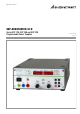


GMC-I Messtechnik GmbH 3
Contents Page
Contents Page
I Initial Inspection . . . . . . . . . . . . . . . . . . . . . . . . . . . . . . . . . .4
II Warnings and Safety Precautions . . . . . . . . . . . . . . . . . . . . .4
1 Technical Description. . . . . . . . . . . . . . . . . . . . . . . . . . . .5
1.1 Features and Range of Applications . . . . . . . . . . . . . . . . . . .5
1.2 Functions . . . . . . . . . . . . . . . . . . . . . . . . . . . . . . . . . . . . . .5
1.3 Options and Accessories . . . . . . . . . . . . . . . . . . . . . . . . . . .6
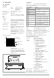
1.4 Functional Principle. . . . . . . . . . . . . . . . . . . . . . . . . . . . . . .6
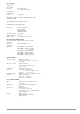
1.5 Technical Data . . . . . . . . . . . . . . . . . . . . . . . . . . . . . . . . . .8
1.5.1 General Data . . . . . . . . . . . . . . . . . . . . . . . . . . . . . . . . . .8
1.5.2 Mechanical Data . . . . . . . . . . . . . . . . . . . . . . . . . . . . . . .9
1.5.3 Electrical Data . . . . . . . . . . . . . . . . . . . . . . . . . . . . . . . .10
2 Initial Start-Up . . . . . . . . . . . . . . . . . . . . . . . . . . . . . . . .12
2.1 Preparing for Operation . . . . . . . . . . . . . . . . . . . . . . . . . . .12
2.1.1 Installing the IEEE 488 Interface Module . . . . . . . . . . . . .12
2.1.2 Installation to 19'' Device Racks . . . . . . . . . . . . . . . . . . .12
2.1.3 Combining Benchtop Devices . . . . . . . . . . . . . . . . . . . . .13
2.1.4 Connection to the Mains . . . . . . . . . . . . . . . . . . . . . . . . .13
2.1.5 Connecting Power Consumers. . . . . . . . . . . . . . . . . . . . .13
2.1.6 Connection to Computer Interfaces . . . . . . . . . . . . . . . . .13
2.2 Switching the Instrument On . . . . . . . . . . . . . . . . . . . . . . .14
3 Controls, Display Elements and Terminals . . . . . . . . . . .16
4 Manual Operation and Device Functions . . . . . . . . . . . .20
4.1 Menu Structure. . . . . . . . . . . . . . . . . . . . . . . . . . . . . . . . .20
4.2 Setting Output Voltage and Output Current . . . . . . . . . . . . .20
4.2.1 Direct Selection (rotary knobs and scroll keys) . . . . . . . . .20
4.2.2 Pre-selected Setting (ENTER, scroll keys) . . . . . . . . . . . .21
4.3
Switching the Power Output On and Off . . . . . . . . . . . . . . . . . . . .21
4.4
Limiting the Allowable Working Range: Ulim, Ilim . . . . . . . . . . . . .22
4.5 Description of OVP and OCP Protection Functions. . . . . . . .22
4.6 Display of Momentary Output Values Uout, Iout and Pout. . .23
4.7 Operating Menu via the FUNCTION Key . . . . . . . . . . . . . . .23
4.7.1 SET – “Setup” Function Group . . . . . . . . . . . . . . . . . . . .25
4.7.2 AnIF – “Analog Interface” Function Group . . . . . . . . . . . .28
4.7.3 SEq – The Sequence Function Group. . . . . . . . . . . . . . . .30
4.7.4 buS – The “Interface” Function Group . . . . . . . . . . . . . . .38
4.8 Settings with the <SELECT> Key
. . . . . . . . . . . . . . . . . . . . . .40
4.8.1 In the Basic Function . . . . . . . . . . . . . . . . . . . . . . . . . . .40
4.8.2
During a Sequence Run and with Step-by-Step Control. . . . . . . .40
4.8.3
Display of Stored Data Upon Execution of <RCL>. . . . . . . . . . . .40
4.8.4 Setting Resolution with the <SELECT> Key . . . . . . . . . . .41
4.9 Storing Data with the <SAVE> Key . . . . . . . . . . . . . . . . . .41
4.9.1 Saving Basic Device Settings. . . . . . . . . . . . . . . . . . . . . .41
4.9.2 Saving Data to a Memory Location. . . . . . . . . . . . . . . . . .41
4.9.3
Clearing the Contents of a Defined Memory Range . . . . . . . . . .42
4.9.4 Inserting a Memory Location . . . . . . . . . . . . . . . . . . . . .43
4.9.5 Deleting a Memory Location . . . . . . . . . . . . . . . . . . . . . .44
4.9.6 Deleting the Contents of a Memory Location . . . . . . . . . .45
4.10 Memory Recall with the <RCL> Key. . . . . . . . . . . . . . . . . .45
4.10.1 Recall from SETUP Memory. . . . . . . . . . . . . . . . . . . . . . .45
4.10.2 Recall from SEQUENCE Memory . . . . . . . . . . . . . . . . . . .46
4.11 Disabling Front Panel Controls . . . . . . . . . . . . . . . . . . . . .46
4.12 <The ENTER> Key . . . . . . . . . . . . . . . . . . . . . . . . . . . . . .46
4.13 The <CE/LOCAL> Key . . . . . . . . . . . . . . . . . . . . . . . . . . .46
4.14 INCR <> and DECR <> Keys . . . . . . . . . . . . . . . . . . . .47
4.15 Device RESET . . . . . . . . . . . . . . . . . . . . . . . . . . . . . . . . .47
4.16
Selecting Remote and Local Control Modes . . . . . . . . . . . . . . . . . 47
5 Analog Interface . . . . . . . . . . . . . . . . . . . . . . . . . . . . . . .48
5.1 Connector Pin Assignments . . . . . . . . . . . . . . . . . . . . . . . .48
5.2 Auto-Sensing Mode . . . . . . . . . . . . . . . . . . . . . . . . . . . . .49
5.3 Status Signal Outputs . . . . . . . . . . . . . . . . . . . . . . . . . . . .49
5.4 Regulating Output Voltage . . . . . . . . . . . . . . . . . . . . . . . .50
5.5 Regulating Output Current . . . . . . . . . . . . . . . . . . . . . . . .50
5.6 Voltage Monitoring Output . . . . . . . . . . . . . . . . . . . . . . . .51
5.7 Current Monitoring Output . . . . . . . . . . . . . . . . . . . . . . . .51
5.8 Trigger Input . . . . . . . . . . . . . . . . . . . . . . . . . . . . . . . . . .52
5.9 Parallel Connection . . . . . . . . . . . . . . . . . . . . . . . . . . . . .52
5.9.1 Direct Parallel Connection . . . . . . . . . . . . . . . . . . . . . . . .52
5.9.2 Master-Slave Parallel Connection . . . . . . . . . . . . . . . . . .54
5.10 Series Connection . . . . . . . . . . . . . . . . . . . . . . . . . . . . . .55
5.10.1 Direct Series Connection. . . . . . . . . . . . . . . . . . . . . . . . .55
5.10.2 Master-Slave Series Connection . . . . . . . . . . . . . . . . . . .56
5.11 Varying the Internal Output Resistance Value . . . . . . . . . . .57
6 Operating Commands . . . . . . . . . . . . . . . . . . . . . . . . . . .58
6.1 Syntax . . . . . . . . . . . . . . . . . . . . . . . . . . . . . . . . . . . . . . .58
6.2 IEEE 488 Functions . . . . . . . . . . . . . . . . . . . . . . . . . . .60
6.3 Overview . . . . . . . . . . . . . . . . . . . . . . . . . . . . . . . . . . . . .60
6.4 Description . . . . . . . . . . . . . . . . . . . . . . . . . . . . . . . . . . . .61
6.5 Status and Events Management. . . . . . . . . . . . . . . . . . . . .77
7 Adjusting the SSP KONSTANTER
CAL – “Calibration” Function Group . . . . . . . . . . . . . . . .79
7.1 General Information and Definition of Terms . . . . . . . . . . . .79
7.2 Adjusting Procedure . . . . . . . . . . . . . . . . . . . . . . . . . . . . .80
7.3 Self-Test Triggering . . . . . . . . . . . . . . . . . . . . . . . . . . . . .82
8 Appendix. . . . . . . . . . . . . . . . . . . . . . . . . . . . . . . . . . . . .83
8.1 Adjustable Functions and Parameters . . . . . . . . . . . . . . . .83
8.2 Queriable Functions and Parameters . . . . . . . . . . . . . . .85
8.3 Query Commands for Status and Events Management . .86
8.4 Overview of Menu Functions . . . . . . . . . . . . . . . . . . . . .87
8.5 Memory Structure . . . . . . . . . . . . . . . . . . . . . . . . . . . . .88
8.6 Indication of Operating States . . . . . . . . . . . . . . . . . . . . . .89
8.7 System Messages. . . . . . . . . . . . . . . . . . . . . . . . . . . . . . .90
8.6 Index . . . . . . . . . . . . . . . . . . . . . . . . . . . . . . . . . . . . . . . .91
9 Order Information . . . . . . . . . . . . . . . . . . . . . . . . . . . . . .92
10 Repair and Replacement Parts Service,
Calibration Center* and Rental Service . . . . . . . . . . . . .92
11 Product Support . . . . . . . . . . . . . . . . . . . . . . . . . . . . . . .92