
User manual


8 GMC-I Messtechnik GmbH
1.5 Technical Data
1.5.1 General Data
Power Supply
Connection Input: 10 A IEC inlet plug
Output: 10 A IEC inlet socket,
without switch,
without fuse
Line voltage 230 V ~ +10 -15%, 47 to 63 Hz
Power consumption See chapter 1.4.3
Inrush Current Max. 50 A
S
Mains fuse 1 ea. T 4 A / 250 V (6.3 x 32 mm, UL)
internal: 1 ea. T 5 A 250 V (5 x 20 mm)
Output
Connection
Output Front panel, 2 ea. 4 mm safety jacks
Rear , 6-pole plug-in screw terminal block
Sensor Rear panel, included in 6-pole plug-in
screw terminal block
Analog interface Rear, 11-pole plug-in screw terminals
Regulator type Primary switched-mode regulator with
BET technology
Operating modes Adjustable constant voltage / constant
current source with automatic sharp
transition
Output isolation Floating output with “safe electrical
separation” from the mains input and
computer interfaces
Max. allowable potential, output–ground:
120 V, capacitance, output–ground
(housing) 60 nF
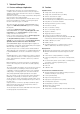
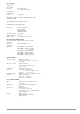
Output operating range
Short-term range:
If lengthy operation in the short-term
range occurs, overtemperature protec-
tion may be triggered resulting in output
shutdown (see also short-term power in
chapter 1.5.3).
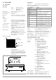
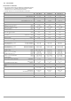
Figure 1.5 Dimensional Drawing (benchtop device)
Analog Interface
Connection 11-pole plug-in screw terminal block
Reference potential Output minus pole, floating TRG input
Connector pin assignments:
Addressable V.24 – RS 232C Interface
Input 9-pin subminiature socket connector
Output 9-pin subminiature plug connector
Operating mode half-duplex, asynchronous, XON / XOFF
Transmission speed adjustable from 50 to 19,200 bits per second
Device address selectable from 0 to 30 or UNL (unlist)
Max. Setting Rate approx. 15 settings per second
Max. Sampling Rateapprox. 7 measurements per second
IEC 625 – IEEE 488 Interface (optional)
Connection 24-pin socket connector
per IEC 625.1, IEEE488.1
Interface SH1 SOURCE HANDSHAKE
functions handshake source function
AH1 ACCEPTOR HANDSHAKE
handshake sink function
T6 TALKER
talker function with serial polling
and automatic unlisting,
no secondary address and no
talk-only operation
L4 LISTENER
listener function with automatic
unlisting, no secondary
address and no listen-only operation
SR1 SERVICE REQUEST
service request function
RL1 REMOTE / LOCAL
remote to local switching
function with disabling
DC1 DEVICE CLEAR
reset function including selected
device clear
PP1 PARALLEL POLL
parallel polling function with remote
configuring
DT1 DEVICE TRIGGER
trigger function
C0 No controller function
E1/2 Open collector driver
Codes / formats Per IEEE 488.2
Device address Selectable from 0 to 30 or UNL (unlist)
Max. setting rate Approx. 40 settings per second
Max. sampling rate Approx. 15 measurements per second
U/V
U
nom
I / A
I
nom
0
0.5 I
nom
P
nom
Short-Term
Working Range
Voltage Setting
Current Setting
0.5
U
nom
Range
Range
380.5
17
14 88
221.5
Dimensions in millimeter
Pin Designation Function
1SIG1 OUT
Digital, programmable, open-collector outputs (max.
30 V / 20 mA)
2SIG2 OUT
3TRG IN –
Digital, programmable control input
(low: < 1.0 V, high: 4 ... 26 V), potential-free
4TRG IN +
5 +15 V
Auxiliary voltage, +15 V / max. 50 mA
reference point, connected to -output
6AGND
7U
set
– Analog, inverting voltage control input
(0 ... –5 V correspond to 0 ... U
nom
, Ri = 10 k)
8U
set
+ Analog voltage control input
(0 ... +5 V correspond to 0 ... U
nom
, Ri = 10 k)
9I
set
+ Analog current control input
(0 ... +5 V correspond to 0 ... I
nom
, Ri = 10 k)
10 U-MON Output voltage measuring output
(0 ... 10 V correspond to 0 ... U
nom
, Ri = 9.8 k)
11 I-MON Output current measuring output
(0 ... 10 V correspond to 0 ... I
nom
, Ri = 9.4 k)