3A6419B EN Important Safety Instructions Read all warnings and instructions in this manual, related manuals, and on the unit. Be familiar with the controls and the proper usage of the equipment. Save these instructions. 888-541-9788 http://magnum.graco.com/magop/ Magnum Products Operational Videos http://magnum.graco.com/magop/ For portable spray applications of architectural paints and coatings only. Not approved for use in explosive atmospheres or hazardous locations.
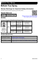
Before You Spray Before You Spray Review Warnings for Important Safety Information Important! Read carefully and practice good safety habits. Related Manuals 312830 3A3172 SG Spray Guns ProXChange™ Pump Magnum Products Operational Videos http://magnum.graco.com/magop/ Models 3000 psi (207 bar, 20.7 MPa) Maximum Working Pressure VAC Model Stand (Series) 17G177 (A) ProX17 17K438 (A) CAN177 (A) ProLTS170 17H198 (A) 120 17G179 (A) 110474 ProX19 USA CAN179 (A) Certified to CAN/CSA C22.2 No.
Contents Contents Before You Spray . . . . . . . . . . . . . . . . . . . . . . . . . . . . . . . . . . . . . . . . . . . . . . . . . . . . . . 2 Warnings . . . . . . . . . . . . . . . . . . . . . . . . . . . . . . . . . . . . . . . . . . . . . . . . . . . . . . . . . . . . . 6 Know Your Sprayer . . . . . . . . . . . . . . . . . . . . . . . . . . . . . . . . . . . . . . . . . . . . . . . . . . . . 10 ProX and ProLTS Stand Models . . . . . . . . . . . . . . . . . . . . . . . . . . . . . . . . . . . . . . .
Contents Maintenance . . . . . . . . . . . . . . . . . . . . . . . . . . . . . . . . . . . . . . . . . . . . . . . . . . . . . . . . . Airless Hoses . . . . . . . . . . . . . . . . . . . . . . . . . . . . . . . . . . . . . . . . . . . . . . . . . . . . . . Spray Tips . . . . . . . . . . . . . . . . . . . . . . . . . . . . . . . . . . . . . . . . . . . . . . . . . . . . . . . . Storage/Priming Tool . . . . . . . . . . . . . . . . . . . . . . . . . . . . . . . . . . . . . . . . . . . . . . . .
Notes Notes 3A6419B EN 5
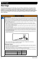
Warnings Warnings The following warnings are for the setup, use, grounding, maintenance, and repair of this equipment. The exclamation point symbol alerts you to a general warning and the hazard symbols refer to procedure-specific risks. When these symbols appear in the body of this manual or on warning labels, refer back to these Warnings. Product-specific hazard symbols and warnings not covered in this section may appear throughout the body of this manual where applicable.
Warnings FIRE AND EXPLOSION HAZARD Flammable fumes, such as solvent and paint fumes, in work area can ignite or explode. To help prevent fire and explosion: • Do not spray flammable or combustible materials near an open flame or sources of ignition such as cigarettes, motors, and electrical equipment. • Paint or solvent flowing through the equipment is able to result in static electricity. Static electricity creates a risk of fire or explosion in the presence of paint or solvent fumes.
Warnings SKIN INJECTION HAZARD High-pressure spray is able to inject toxins into the body and cause serious bodily injury. In the event that injection occurs, get immediate surgical treatment. • Do not aim the gun at, or spray any person or animal. • Keep hands and other body parts away from the discharge. For example, do not try to stop leaks with any part of the body. • Always use the nozzle tip guard. Do not spray without nozzle tip guard in place. • Use Graco nozzle tips.
Warnings PRESSURIZED ALUMINUM PARTS HAZARD Use of fluids that are incompatible with aluminum in pressurized equipment can cause serious chemical reaction and equipment rupture. Failure to follow this warning can result in death, serious injury, or property damage. • Do not use 1,1,1-trichloroethane, methylene chloride, other halogenated hydrocarbon solvents or fluids containing such solvents. • Do not use chlorine bleach. • Many other fluids may contain chemicals that can react with aluminum.
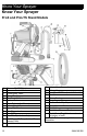
Know Your Sprayer Know Your Sprayer ProX and ProLTS Stand Models A B C D E F G H J K L M N O 10 Power - ON/OFF Switch Pressure Control Knob Prime/Spray Valve Spray Tip PushPrime™ Button Suction Tube Drain Tube (with diffuser) Airless Spray Gun Spray Tip Guard Gun Trigger Lock Gun Fitting Gun Filter (inside handle) ProXChange™ Pump (behind Easy Access Door) Inlet Valve P Q R T U V W X Y Z Airless Hose Connection Airless Hose InstaClean™ Filter (inside fluid outlet) Inlet Screen Power Cord Easy Access Do
Know Your Sprayer Know Your Sprayer ProX and ProLTS Cart Models A B C D E F G H J K L M N O Power - ON/OFF Switch Pressure Control Knob Prime/Spray Valve Spray Tip PushPrime Button Suction Tube Drain Tube (with diffuser) Airless Spray Gun Spray Tip Guard Gun Trigger Lock Gun Fitting Gun Filter (inside handle) ProXChange™ Pump (behind Easy Access Door) Inlet Valve 3A6419B EN P Q R S T U V X Y Z Airless Hose Connection Airless Hose InstaClean Filter (inside fluid outlet) Pail Hanger Inlet Screen Power Co
Know Your Controls Know Your Controls The ON/OFF power switch controls the main power to your sprayer. The Pressure Control knob increases or decreases the pressure and flow of the paint. The Prime/Spray Valve directs the fluid to either the Drain Tube or the hose and gun. It is used to prime the sprayer, which means to evacuate the air out of the pump, hose, and gun. Your gun will not spray if there is air in the system.
Set Up Set Up Assemble Your Sprayer 1. Connect airless hose to airless hose connection (P) on sprayer. Use wrench to tighten securely. 2. Connect the other end of the hose to the gun. Use two wrenches to tighten securely to gun (see image below). 3. Assure Spray Tip is properly inserted into the Spray Tip Guard, and the Spray Tip Guard assembly is tightened securely to gun. See Spray Tip Installation, page 21. 4. Perform the Pressure Relief Procedure, page 14.
Start Up Start Up Pressure Relief Procedure 3. Turn pressure control knob to lowest setting. 4. Put Drain Tube into a waste pail and turn Prime/Spray Valve down to PRIME position to relieve pressure. 5. Hold the gun firmly to a pail. Point gun into pail. Disengage the trigger lock and trigger the gun to relieve pressure. 6. Engage the trigger lock. 7. If you suspect that pressure has not been fully relieved, see Blockages, page 17.
Start Up Flush Storage Fluid 7. Align setting indicator with the START setting on the pressure control knob. 8. Turn ON/OFF switch to ON position. 9. When sprayer starts pumping, flushing fluid will flow up the Suction Tube and out the Drain Tube. Allow fluid to flow out of Drain Tube, into waste pail, for 30 to 60 seconds. It is important that you flush storage fluid from the sprayer before using it. 1. Make certain ON/OFF switch is OFF. 2.
Start Up Strain the Paint Disposable paint strainer bags are used to remove coarse particles and debris from new or previously opened paint or stain, and are available where paint is sold. To avoid priming problems and Spray Tip clogs it is recommended to strain all paints and stains before spraying. Stretch a disposable paint strainer bag over a clean pail and pour the paint through the strainer. 2. Turn ON/OFF switch to ON position. 3. Wait to see paint coming out of Drain Tube. 4.
Start Up 4. Release trigger. Engage trigger lock. Refilling Paint Pail When the paint pail runs low and the gun stops spraying, refill the paint pail and repeat the Fill Pump (Prime Pump) procedure, then the Fill Gun and Hose procedure. You are now ready to spray! High-pressure spray is able to inject toxins into the body and cause serious bodily injury. Do not stop leaks with hand or rag. NOTE: It is normal for the motor to stop once the sprayer is primed and under pressure.
Spraying Spraying Start 1. Turn pressure control knob to START position. 2. Disengage trigger lock. Adjust Pressure Control To select a setting, align symbol on pressure control knob with setting indicator on sprayer. 1. For best spray results with lowest overspray, adjust pressure control to “START” setting. 2. Test the spray pattern on a test area or piece of cardboard. 3. If needed, increase Pressure Control Knob setting to minimum setting that results in an acceptable spray pattern.
Spraying Spray Techniques Use a piece of scrap cardboard to practice these basic spraying techniques before you begin spraying the surface. • Hold gun 12 in. (30 cm) from surface and aim straight at surface. Tilting gun to direct spray angle causes an uneven finish. • Flex wrist to keep gun pointed straight. Fanning gun to direct spray at angle causes uneven finish. Aiming Gun Aim center of spray of gun at bottom edge of previous stroke, overlapping each stroke by half.
Spraying Spray Tip and Pressure Selection Spray Tips come in a variety of sizes for spraying a wide range of materials. Your sprayer includes a 515 Spray Tip for use with most paints on large surfaces such as walls and ceilings. If you are spraying stain or need a different spray fan width, refer to the Spray Tip chart below to select the best Spray Tip for your project. Additional Spray Tip sizes are available where paint sprayers are sold. 1.
Spraying Clear Spray Tip Clog 2. Engage trigger lock. Rotate Spray Tip back to SPRAY position. Disengage trigger lock and continue spraying. SPRAY In the event that particles or debris clog the Spray Tip, the Spray Tip can be reversed to quickly and easily clear particles without disassembling the sprayer. See Strain the Paint, page 16 for additional information. 1. Engage trigger lock. Rotate Spray Tip to UNCLOG position.
Spraying a. Use Spray Tip to align gasket and seal in the Spray Tip Guard. c. 4. b. 22 Turn the arrow shaped handle on the Spray Tip forward to the SPRAY position. Screw Spray Tip Guard assembly onto the gun and tighten. Spray Tip must be pushed all the way into the Spray Tip Guard. Rotate Spray Tip while pushing down.
Cleanup Cleanup Cleaning the sprayer after each use results in a trouble free start up the next time the sprayer is used. 4. Separate Drain Tube (smaller) from Suction Tube (larger). ti27 7124a • For short term shutdown periods (overnight to two days), refer to Short Term Storage, page 28. • For cleanup after using water-based materials only (by use of a garden hose), refer to Cleanup with Power Flush Valve, page 25. • For cleanup from pails, refer to Cleaning from a Pail, below.
Cleanup 8. Turn Prime/Spray valve down to PRIME position. e. Continue to hold gun trigger until you see paint diluted with flushing fluid starting to come out of gun. 13. While continuing to trigger gun, quickly move gun to redirect spray into waste pail. Continue triggering gun into waste pail until flushing fluid dispensed from gun is relatively clear. 9. Turn ON/OFF switch to ON position. 10. Flush until approximately 1/3 of the flushing fluid is emptied from the pail. 11.
Cleanup Cleanup with Power Flush Valve 7. Screw Power Flush Valve (included with sprayer) to garden hose. Close Power Flush Valve. (Water-based materials only) 8. Turn on water. Open Power Flush Valve. Rinse paint off Suction Tube, Drain Tube and inlet screen. Close Power Flush Valve. 9. Unscrew inlet screen from Suction Tube. Place inlet screen in waste pail. Connect garden hose to Power Flush Valve on Suction Tube. Leave Drain Tube in waste pail. Power flushing is a faster method of cleanup.
Cleanup c. d. e. Turn Prime/Spray Valve horizontal to SPRAY position (C). Turn ON/OFF switch to ON position (D). 16. Turn pressure control knob to the lowest setting. 17. Stop triggering gun. Engage the trigger lock. Continue to hold gun trigger until you see paint diluted with flushing fluid starting to come out of gun. 18. Turn Prime/Spray Valve down to PRIME position. 19. Turn ON/OFF switch to OFF position. 20. Follow Short Term Storage or Long Term Storage, page 28. 15.
Cleanup Cleaning InstaClean Filter The InstaClean Filter prevents debris from entering paint hose. After each use, remove and clean it to ensure peak performance. 1. Perform Pressure Relief Procedure, page 14. 2. Disconnect airless spray hose (A) from sprayer. 3. Unscrew fluid outlet (B). 4. Remove InstaClean filter (C). C Clean the Gun and Gun Filter 1. Perform Pressure Relief Procedure, page 14. 2. Remove the gun handle by unscrewing the handle from the gun head. 3.
Storage Storage With proper storage, the sprayer will be ready to use the next time it is needed. 4. Engage trigger lock. ti25196b 5. Leave gun attached to hose. 6. Remove Spray Tip and Spray Tip Guard and clean with water or flushing fluid and a brush. 7. Wipe paint off outside of gun using a soft cloth moistened with water or flushing fluid. Short Term Storage (up to 2 days) 1. Disconnect power (unplug power cord). Perform Pressure Relief Procedure, page 14. 2.
Storage 4. Place drain tube in waste pail. Turn pressure control to the START position. 7. Screw Inlet Screen back to Suction Tube. Ensure that spray gun and hose stay attached to sprayer. 5. ProX21 only: Place Suction Tube in Pump Armor fluid bottle. Turn Power Switch ON. 8. Turn Spray/Prime Valve horizontal to SPRAY position for storage. 9. Turn ON/OFF switch to OFF position. Disconnect power (unplug power cord).
Reference Reference Lacquer Conversion Kit To spray lacquers and other solvent-based flammable materials with models other than ProX21, you must purchase a lacquer conversion kit and follow Static Grounding Instructions (Oil or Solvent-Based Flammable Materials), page 30. Refer to Parts List for kit part numbers. Cleaning Fluid Compatibility Static Grounding Instructions (Oil or Solvent-Based Flammable Materials) The equipment must be grounded to reduce the risk of static sparking.
Reference Quick Reference Page 10 Name A B Power - ON/OFF Switch Pressure Control Knob C Prime/Spray Valve D Spray Tip E F G PushPrime Button Suction Tube Drain Tube H J K L M Airless Spray Gun Spray Tip Guard Gun Trigger Lock Gun Fitting Gun Filter (inside handle) N ProXChange™ Pump O P Q R Inlet Valve Airless Hose Connection Airless Hose InstaClean Filter S T U V Pail Hanger Inlet Screen Power Cord Easy Access Door W X Suction Tube Drip Cup Pump Removal Tool Y Z Outlet Valve Inlet Val
Maintenance Maintenance Routine maintenance is important to ensure proper operation of your sprayer. Maintenance Activity 1. 2. Inspect motor shroud openings for blockage every time you spray. Clean/inspect inlet screen, InstaClean filter, and gun filter every time you spray. Replace if the filter cannot be cleaned or is damaged. NOTICE Storage/Priming Tool Perform these steps if you are experiencing difficulty priming your sprayer. For ProX21, see Inlet Valve Removal, page 33. 1.
Maintenance 4. Squeeze Pump Armor bottle until Pump Armor flows into the Drain Tube. Inlet Valve Removal An integrated tool is included in the frame to remove the inlet valve assembly from the pump. If you suspect that the inlet valve is clogged or stuck, remove the valve assembly and clean or replace. 1. 5. Insert pump inlet into frame and loosen the inlet valve. Remove inlet valve. Remove tool. Replace and tighten child-proof cap for storage. ti27479a 2. Remove inlet valve.
Maintenance 3. Perform a power flush. See Cleanup with Power Flush Valve, page 25. 3. Now lift the door so that it swings out of the way. 1 High-pressure spray is able to inject toxins into the body and cause serious bodily injury. Do not stop leaks with hand or rag. 4. Inspect for leaks. If leaks occur, perform Pressure Relief Procedure, page 14, then tighten all fittings and repeat step 3. 2 Pump Repair 3 When pump packings wear, paint will begin to leak down outside of pump.
Maintenance ProXChange Removal Tool a. Move pump rod up or down until cap is level with the opening in the yoke. b. Push on pump rod to slide pump assembly back on to mounting pins. An integrated tool is included in the frame to remove the ProXChange packing assembly. See ProXChange Pump manual for complete repair instructions. ti27037a 2. Swing Easy Access Door closed while pushing the entire door down. 1 ti26931a Pump Installation 1. Slide pump assembly onto the mounting pins.
Troubleshooting Troubleshooting 3. Check everything in this Troubleshooting Table before you bring the sprayer to an authorized service center. Have a Question? Call Us Toll-Free: 1-888-541-9788 1. 2. Follow Pressure Relief Procedure, page 14, before checking or repairing. Solutions at the beginning of each problem listed are the most common. Problem Motor does not run: (verify sprayer is plugged in, and ON/OFF switch is on) 36 or visit us at: www.magnum.graco.
Troubleshooting Problem Sprayer runs, but pump does not prime or looses prime while in use. (Pump cycles but does not pull paint into Suction Tube or build pressure.) Cause Solution Prime/Spray Valve is in SPRAY position. Turn Prime/Spray Valve down to PRIME position until paint exits Drain Tube. Inlet screen is clogged or Suction Tube is not completely immersed in paint. Clean debris off inlet screen and make sure Suction Tube is completely immersed in paint.
Troubleshooting Problem Pump is primed, but can not achieve good spray pattern. 38 Cause Solution Spray Tip may be partially clogged. See Clear Spray Tip Clog, page 21. Reversible Spray Tip is in UNCLOG position. Rotate arrow-shaped handle on Spray Tip so it points forward to SPRAY position. See page 21. Debris in paint causing obstruction. Strain the paint. See Clear Spray Tip Clog, page 21. Pressure is set too low. Align pressure control knob setting indicator to desired spray setting.
Troubleshooting Problem Cause Solution Spray gun stopped spraying while trigger is pulled. Spray Tip is clogged. See Clear Spray Tip Clog, page 21 Sprayer lost prime. Reprime sprayer. See Fill Pump (Prime Pump), page 16. When paint is sprayed, it runs down the wall or sags. Material is going on too thick. See Troubleshooting, page 36. Move gun faster. Choose a Spray Tip with smaller hole size. Choose Spray Tip with wider fan. Make sure gun is far enough from surface.
ProX17, ProX19, ProLTS170 Stand Sprayer ProX17, ProX19, ProLTS170 Stand Sprayer Parts Ref. Torque 1 140-160 in-lb (16-18 N•m) 2 30-35 in-lb (3.5-4.0 N•m) 3 110-120 in-lb (12-14 N•m) 4 45-55 in-lb (5-6 N•m) 2 2 2 1 See page 48.
ProX17, ProX19, ProLTS170 Stand Sprayer ProX17, ProX19, ProLTS170 Stand Sprayer Parts List Ref. Part Description 1 17F756 1a 2 3 4 6 287770 17J863 17J173 17J864 117493 7 8 17J874 17J865 9 118444 10 17J866 KIT, repair, motor, 120V includes 1a, 22 FAN KIT, gear and yoke CORD, power KIT, yoke SCREW, mach, hex, washer head KIT, pump complete SHIELD, motor, blue includes 9 and labels SCREW, mach, hwhd 10-24 x 0.5 in.
ProX21 Stand Sprayer Parts ProX21 Stand Sprayer Parts Ref. Torque 1 140-160 in-lb (16-18 N•m) 2 30-35 in-lb (3.5-4.0 N•m) 3 110-120 in-lb (12-14 N•m) 2 2 2 1 See page 48.
ProX21 Stand Sprayer Parts ProX21 Stand Sprayer Parts List Ref. Part 1 Description MOTOR, 120V includes 1a, 22 17K684 Series A 17F757 Series B 1a 16X980 FAN 2 17J869 KIT, gear and yoke 3 17J173 CORD, power 4 17J864 KIT, yoke 6 117493 SCREW, mach, hex, washer head 7 17J875 KIT, pump complete 8 SHIELD, motor, blue includes 9, 56 17K688 Series A 17J865 Series B 9 118444 SCREW, mach, hwhd 10-24 x 0.5 in.
ProX17, ProX19, ProLTS190 Cart Sprayer ProX17, ProX19, ProLTS190 Cart Sprayer Parts Ref. Torque 2 30-35 in-lb (3.5-4.0 N•m) 3 110-120 in-lb (12-14 N•m) 4 45-55 in-lb (5-6 N•m) 2 2 2 2 3 4 See page 48.
ProX17, ProX19, ProLTS190 Cart Sprayer ProX17, ProX19, ProLTS190 Cart Sprayer Parts List Description Ref. Part Qty. 1 17F756 MOTOR, 120V 1 includes1a, 22 1a 287770 FAN 1 2 17J863 KIT, gear and yoke 1 3 17J173 CORD, power 1 4 17J864 KIT, yoke 1 7 17J874 KIT, pump complete 1 8 17J865 SHIELD, motor, blue 1 includes 9 and labels 9 118444 SCREW, mach, hwhd 3 10-24 x 0.5 in.
ProX21 Cart Sprayer Parts ProX21 Cart Sprayer Parts Ref. Torque 2 30-35 in-lb (3.5-4.0 N•m) 3 110-120 in-lb (12 -14 N•m) 2 2 2 2 3 3 46 See page 48.
ProX21 Cart Sprayer Parts ProX21 Cart Sprayer Parts List Ref. Part 1 Description KIT, repair, motor, 120V includes 1a, 22 17K684 Series A 17F757 Series B 1a 16X980 FAN 2 17J869 KIT, gear and yoke 3 17J173 CORD, power 4 17J864 KIT, yoke 7 17J875 KIT, pump complete 8 SHIELD, motor, blue includes 9, 56 17K688 Series A 17J865 Series B 9 118444 SCREW, mach, hwhd 10-24 x 0.5 in.
ProXChange Pump Parts ProXChange Pump Parts Ref. Torque 1 140-160 in-lb (16-18 N•m) 2 30-35 in-lb (3.4-4.
ProXChange Pump Parts ProXChange Pump Parts List i Ref. 1 2 3 4 5 6 6a 7 7a 7b 8 9 10 11 12 Part 17G447 17D364 128336 105445 117501 Description HOUSING, pump GUIDE, ball SPRING, compression BALL, 0.5 in.
Wiring Diagram - 110/120V Wiring Diagram - 110/120V M ti27233a 50 3A6419B EN
Notes Notes 3A6419B EN 51
Technical Specifications Technical Specifications Sprayer Maximum fluid working pressure Maximum Delivery ProX17, ProLTS170 ProX19, ProLTS190 ProX21 Maximum Spray Tip Size ProX17, ProLTS170 ProX19, ProLTS190 ProX21 Fluid Outlet npsm Generator Minimum Power Requirements ProX17, ProX19, ProLTS170, ProLTS190 ProX21 Dimensions Height ProX17, ProX19, ProLTS170 Stand ProX21 Stand ProX17 Cart ProX19, ProLTS190 Cart ProX21 Cart Length ProX17, ProX19, ProLTS170 Stand ProX21 Stand ProX17 Cart ProX19, ProLTS190 Cart P
Technical Specifications ProX21 Stand ProX17 Cart ProX19, ProLTS190 Cart ProX21 Cart Storage temperature range Operating temperature range Materials of Construction Wetted materials on all models US 25.0 lb. 37.5 lb. 41.2 lb. 49.5 lb. Metric 11.3 kg 17.0 kg 18.7 kg 22.
Graco Standard Warranty Graco Standard Warranty Graco warrants all equipment referenced in this document which is manufactured by Graco and bearing its name to be free from defects in material and workmanship on the date of sale to the original purchaser for use. With the exception of any special, extended, or limited warranty published by Graco, Graco will, for a period of twelve months from the date of sale, repair or replace any part of the equipment determined by Graco to be defective.
Graco Information Graco Information For the latest information about Graco products, visit www.graco.com. For patent information, see www.graco.com/patents. TO PLACE AN ORDER, contact your Graco distributor or call 1-800-690-2894 to identify the nearest distributor.
All written and visual data contained in this document reflects the latest product information available at the time of publication. Graco reserves the right to make changes at any time without notice. Original instructions. This manual contains English. MM 3A6419 Graco Headquarters: Minneapolis International Offices: Belgium, China, Japan, Korea GRACO INC. AND SUBSIDIARIES • P.O. BOX 1441 • MINNEAPOLIS MN 55440-1441 • USA Copyright 2018, Graco Inc.