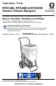
Operation, Parts RTX1400, RTX2000 & RTX2500 3A3258J Interior Texture Sprayers EN For water-based materials only. For professional use only. Models: RTX1400si, RTX2000pi & RTX2500pi 70 psi (4.8 bar, 0.48 MPa) Maximum Working Pressure 100 psi (6.9 bar, 0.69 MPa) Maximum Working Pressure (RTX2500pi) Important Safety Instructions Read all warnings and instructions in this manual and related manuals. Be familiar with the controls and the proper usage of the equipment. Save these instructions.
Contents Contents Models . . . . . . . . . . . . . . . . . . . . . . . . . . . . . . . . . . . . . . . . . . . . . . . . . . . . . . . . . . . . . . . 3 Warnings . . . . . . . . . . . . . . . . . . . . . . . . . . . . . . . . . . . . . . . . . . . . . . . . . . . . . . . . . . . . . 4 Component Identification . . . . . . . . . . . . . . . . . . . . . . . . . . . . . . . . . . . . . . . . . . . . . . . . 7 RTX1400si . . . . . . . . . . . . . . . . . . . . . . . . . . . . . . . . . . . . . . . . . . . . . .
Models Models VAC Model RTX1400si RTX1400si RentalHD RTX2000pi RTX2000pi Rental RTX2000pi RentalHD 17H572 17P189 17H573 17H574 17K301 120 USA RTX2500pi RTX2500pi Rental RTX2500pi Rental HD 17U219 17U220 17U221 230 AP RTX1400pi 17X738 230 AP SCA Europe RTX2500pi 17V582 120 USA 110474 Certified to CAN/CSA C22.2 No.
Warnings Warnings The following warnings are for the setup, use, grounding, maintenance, and repair of this equipment. The exclamation point symbol alerts you to a general warning and the hazard symbols refer to procedure-specific risks. When these symbols appear in the body of this manual or on warning labels, refer back to these Warnings. Product-specific hazard symbols and warnings not covered in this section may appear throughout the body of this manual where applicable.
Warnings FIRE AND EXPLOSION HAZARD Flammable fumes, such as solvent and paint fumes, in work area can ignite or explode. To help prevent fire and explosion: • Do not spray or clean with flammable materials. Use water-based materials only. • Use equipment only in well ventilated area. • Sprayer generates sparks. When flammable liquids are used near the sprayer, keep sprayer at least 20 feet (6.1 meters) away from explosive vapors. • Keep work area free of debris, including solvent, rags and gasoline.
Warnings PRESSURIZED EQUIPMENT HAZARD Fluid from the equipment, leaks, or ruptured components can splash in the eyes or on skin and cause serious injury. • Follow the Pressure Relief Procedure when you stop spraying/dispensing and before cleaning, checking, or servicing equipment. • Tighten all fluid connections before operating the equipment. • Check hoses, tubes, and couplings daily. Replace worn or damaged parts immediately.
Component Identification Component Identification RTX1400si P W S R Y A E N M B C H J K F G D ti27337a A B C D E F G H J Handle Toolbox Power Cord Pump Access Panel RotoFlex™ II Pump Pump Hose Outlet Air Hose Outlet Material Flow Gauge Material Flow Control 3A3258J K M N P R S W Y ON/OFF Switch Material Hopper Burp Guard Material/Air Hose Material Thickness Gauge Nozzle Gun Air control valve Model/Serial Tag (Not shown, located on bottom of unit.
Component Identification RTX2000pi & RTX2500pi P W S R Y X A N M B C H J K F G D A B C D E F G H J K 8 Handle Toolbox Power Cord Pump Access Panel RotoFlex™ II Pump Pump Hose Outlet Air Hose Outlet Material Flow Gauge Material Flow Control ON/OFF Switch ti27338a M N P R S W X Y Material Hopper Burp Guard Material/Air Hose Material Thickness Gauge Nozzle & retaining ring Gun Prime Valve Air control valve Model/Serial Tag (Not shown, located on bottom of unit.
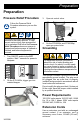
Preparation Preparation Pressure Relief Procedure 3. Open air control valve. Follow the Pressure Relief Procedure whenever you see this symbol. This equipment stays pressurized until pressure is manually relieved. To help prevent serious injury from pressurized fluid or splashed fluid follow the Pressure Relief Procedure whenever sprayer is stopped and before sprayer is cleaned or checked, and before equipment is serviced. 1. Turn ON/OFF switch to the OFF position.
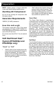
Preparation NOTE: Lighter gauge or longer extension cords may reduce sprayer performance. Auxiliary Air Compressor Do not use an auxiliary air compressor with this spray system. Generator Requirements 3500 W (3.5 kW) minimum. Hose Size and Length The system comes with a 25 ft (7.6m) hose set consisting of a 3/4 in. ID RTX1400si/1 in. ID RTX2000pi and RTX2500pi material hose and a 3/8 in-ID air hose. Do not use more than 25 ft (7.6 m) of material hose.
Setup Setup 4. Connect material hose to gun. NOTICE • • Do not store sprayer under pressure. • When operating a RTX1400SI and you are going to stop spraying for more than five minutes turn sprayer OFF to prevent shortened pump life. 1. Connect air hose and material hose to sprayer air and material hose outlets. Do not allow material to dry inside pump, hoses, gun or spray system. ti27344a 5. Make sure burp guard is installed. Before adding material to the hopper, install the burp guard.
Setup 7. Pour one gallon (four liters) of water into the material hopper. NOTICE 10. Point gun into waste bucket and pull trigger to pump water through the system. Continue to trigger gun until material hopper is empty. To prevent pump damage, before adding material or starting unit in cold weather, run warm water through the pump. ti27381a 11. Add pre-mixed texture mix to material hopper. See Mixing Material, page 13. ti27346a 8. Turn ON/OFF switch to ON position. ti27380a 9.
Mixing Material Mixing Material Premix Slowly add approximately 2 to 4 quarts (1.9 to 3.8 liters) of water to a 5 gallon (18.9 liter) bucket of premix. NOTE: Correct material mixture is essential. The pump will not operate if the mixture is too thick. • Mix the material in a separate container before pouring it into hopper. • Use Material Thickness Gauge to determine if mixture is thin enough to spray.
Mixing Material NOTE: For an accurate test, be sure gauge is completely dry and clean every time it is used. 6. If the ball does not sink completely into the mixture within 10 seconds, add more water, agitate and try test again. 5. 7. Once material is mixed pour material into the sprayer hopper. See Operation, page 15 for nozzle selection and sprayer adjustments. Observe the ball on the material.
Operation Operation Texture Spraying Recommended Nozzle Selection Charts RTX1400si 120V Application Nozzle Size2 Air Volume1 Application Simulated Acoustic 6 mm, white medium to high (fine to medium) 8 mm, gray (coarse) Orange peel 4 mm, beige, medium to high 6 mm, white 1Control air volume with gun air valve. Nozzle Size2 Air Volume1 Splatter coat 6 mm, white low to medium 8 mm, gray Knockdown 6 mm, white 8 mm, gray 12 mm, black low 2For more material volume try a larger nozzle.
Operation + Opening air valve increases air flow through gun, which decreases texture material flow through pump. + Closing air valve decreases air flow through gun, which increases texture material flow through pump. To achieve uniform spray pattern, adjust air valve and flow adjustment nut on gun. If you do not achieve the desired pattern, change nozzles, see Recommended Nozzle Selection Charts, page 15. • Point gun away from surface you are spraying when you first pull trigger.
Shutdown and Cleanup Shutdown and Cleanup NOTE: Keep pump and hose clean when switching between simulated acoustic, knockdown and orange peel applications. A dirty pump can release particles of texture into the finish. • To increase pump life, life turn power OFF when not spraying. • Before removing material hose, perform Pressure Relief Procedure, page 9. Make certain there is no material in the hose.
Shutdown and Cleanup 6. Spray inside material hopper to circulate water through gun and hose. While circulating water, use gun to clean material hopper. ti27340a ti27339a 10. Open gun air valve. Perform pressure relief procedure, Pressure Relief Procedure, page 9. 7. Partially open gun air valve to use air to achieve better cleaning results. Air hose fittings can get hot. Allow sprayer to cool down 15 minutes before removing air hose.
Shutdown and Cleanup 3. Plug opening on bottom of material hopper with your hand. NOTICE Water or material remaining in unit when temperatures are below freezing can damage motor and/or delay pump startup. Do not allow unit to freeze. To ensure water and material are completely drained out of unit: ti27388a 4. Take hopper to cleaning area for cleaning. 5. After cleaning material hopper, position it on sprayer handle first. 1. Remove material hose from sprayer. 2. Remove pump hose from sprayer.
Maintenance Maintenance Routine maintenance is important to ensure proper operation of your sprayer. Maintenance includes performing routine actions which keep your sprayer in operation and prevent trouble in the future. Activity Interval Inspect motor shield vents for blockage. Daily or each time you spray Every 1000 gallons (3785 Check sprayer stall (RTX2000pi and RTX2500pi only). With sprayer gun NOT triggered, sprayer motor should stall liters) and not restart until gun is triggered again.
Troubleshooting Troubleshooting 1. Follow Pressure Relief Procedure, page 9, before checking or repairing. Problem Sprayer won’t run Pump won’t pump material Material runs out of bottom of sprayer No air from compressor 3A3258J 2. Check all possible problems and causes before disassembling the unit. Cause Solution Power switch not on Turn switch on. No power at wall outlet Check outlet by plugging in another appliance. If appliance does not work, try another outlet.
Troubleshooting Problem Speed of application slow or slower Cause Solution Material too thick Thin material. Nozzle too small Change nozzles to a larger size. See Recommended Nozzle Selection Chart, page 15. Too much air being used. Partially close gun air valve to reduce air flow. Pump hose worn Replace hose. Plugged or dirty gun Perform Pressure Relief Procedure, page 9. Clean gun. Kinked hose Unkink hose. Gun adjustment set too low Increase flow adjustment with flow adjustment nut.
Troubleshooting Problem Cause Solution Power switch is on and sprayer is plugged in, but motor does not run, and pump does not cycle. Air valve on gun is closed or not open enough. Open air valve. Motor or control is damaged. Take sprayer to Graco authorized service center. Electric outlet is not providing power. Try a different outlet or plug in something that you know is working to test outlet. Reset building circuit breaker or replace fuse. Extension cord is damaged. Replace extension cord.
RTX1400si Sprayer RTX1400si Sprayer Ref. Torque Ref. Torque 1 15-20 in-lb (1.7 - 2.3 N•m) 5 27-32 in-lb (3.1 - 3.6 N•m) 2 75-95 in-lb (8.5 - 10.7 N•m) 6 90-110 in-lb (10.2 - 12.4 N•m) 3 50-70 in-lb (5.6 - 7.9 N•m) 8 4 40-50 in-lb (4.5 - 5.6 N•m) 65-85 in-lb (7.3 - 9.
RTX1400si Sprayer RTX1400si Sprayer (cont’d) Ref. Torque Ref. Torque 1 15-20 in-lb (1.7 - 2.3 N•m) 5 27-32 in-lb (3.1 - 3.6 N•m) 2 75-95 in-lb (8.5 - 10.7 N•m) 6 90-110 in-lb (10.2 - 12.4 N•m) 3 50-70 in-lb (5.6 - 7.9 N•m) 8 4 40-50 in-lb (4.5 - 5.7 N•m) 65-85 in-lb (7.3 - 9.6 N•m) then back off 1/4 turn 21 3 29 60 80 2 16 8 26 See page 34.
RTX1400si Sprayer RTX1400si Sprayer Parts List Ref. Part 1 2 3 4 5 6 7 8 9 10 11 12 13 14 15 17U971 15J600 15H069 17H404 17K497 277319 15J672 15J671 110755 17K546 112612 17H418 17K511 102313 288336 16 19 21 23 288623 120660 15H910 17P499 25 26 27 29 30 31 32 33 35 17H410 105240 113981 17W832 117633 120771 17H490 24Z003 120236 17B440 36 38 40 120731 289591 16M501 17V511 42 15J862 43 15D561 47 120759 49 115498 50 104227 51 15H841 17V739 52 15K616 26 Description Qty.
RTX2000pi Sprayer RTX2000pi Sprayer Ref. Torque Ref. Torque 1 15-20 in-lb (1.7 - 2.3 N•m) 5 27-32 in-lb (3.1 - 3.6 N•m) 2 75-95 in-lb (8.5 - 10.7 N•m) 6 90-110 in-lb (10.2 - 12.4 N•m) 3 50-70 in-lb (5.6 - 7.9 N•m) 8 65-85 in-lb (7.3 - 9.6 N•m) then back off 1/4 turn 4 40-50 in-lb (4.5 - 5.7 N•m) 9 3-5 in-lb (0.34-0.56 N•m) Loctite 243 2 2 1 1 8 8 3 4 2 5 2 5 3A3258J See page 34.
RTX2000pi Sprayer RTX2000pi Sprayer (cont’d) Ref. Torque Ref. Torque 1 15-20 in-lb (1.7 - 2.3 N•m) 6 90-110 in-lb (10.2 - 12.4 N•m) 2 75-95 in-lb (8.5 - 10.7 N•m) 7 9-11 in-lb (1- 1.2 N•m) 3 50-70 in-lb (5.6 - 7.9 N•m) 8 4 40-50 in-lb (4.5 - 5.7 N•m) 9 5 27-32 in-lb (3.1 - 3.6 N•m) 65-85 in-lb (7.3 - 9.6 N•m) then back off 1/4 turn 120-130 in-lb (13.6 - 14.7 N•m) 1 8 2 8 See page 34. See page 36.
RTX2000pi Sprayer RTX2000pi Sprayer Parts List Ref.
RTX2500pi Sprayer RTX2500pi Sprayer Ref. Torque Ref. Torque 1 15-20 in-lb (1.7 - 2.3 N•m) 5 27-32 in-lb (3.1 - 3.6 N•m) 2 75-95 in-lb (8.5 - 10.7 N•m) 6 90-110 in-lb (10.2 - 12.4 N•m) 3 50-70 in-lb (5.6 - 7.9 N•m) 8 65-85 in-lb (7.3 - 9.6 N•m) then back off 1/4 turn 4 40-50 in-lb (4.5 - 5.7 N•m) 9 3-5 in-lb (0.34-0.56 N•m) Loctite 243 2 2 1 1 8 5 3 8 4 2 5 2 5 30 2 See page 34.
RTX2500pi Sprayer RTX2500pi Sprayer (cont’d) Ref. Torque Ref. Torque 1 15-20 in-lb (1.7 - 2.3 N•m) 6 90-110 in-lb (10.2 - 12.4 N•m) 2 75-95 in-lb (8.5 - 10.7 N•m) 7 9-11 in-lb (1- 1.2 N•m) 3 50-70 in-lb (5.6 - 7.9 N•m) 8 4 40-50 in-lb (4.5 - 5.7 N•m) 9 5 27-32 in-lb (3.1 - 3.6 N•m) 65-85 in-lb (7.3 - 9.6 N•m) then back off 1/4 turn 120-130 in-lb (13.6 - 14.7 N•m) 1 8 2 8 See page 34. See page 36.
RTX2500pi Sprayer RTX2500pi Sprayer Parts List Ref.
Notes Notes 3A3258J 33
Compressor Parts Compressor Parts Ref. 1 2 Torque Ref. 18-22 ft-lb (24.4 - 29.8 N•m) 50-65 in-lb (5.7 - 7.3 N•m) 5 120-140 in-lb (13.6 - 15.8 N•m) Finger tighten cap screw in position 1 first. Then torque cap screws in 2, 3, 4, and 1 sequence illustrated. 6 190-230 in-lb (21.5 - 26 N•m) 3 Piston retaining bolt & crankshaft bolts must torqued before head bolts (30) are torqued. 4 60-72 in-lb (6.8 - 8.1 N•m) Torque Hand tighten, then 2 full turns 8 Tension to 15-25 lb (66.7-111.
Compressor Parts Compressor Parts List Ref.
Flow Switch Assembly Flow Switch Assembly Ref. 5 Torque 27-32 in-lb (3.1 - 3.6 N•m) 5 36 Ref. Part Description 17Z247 1 19A549 2 19A550 3 113418 4 19A551 5 130785 6 130786 7 104444 8 17V538 9 101970 10 127343 11 113444 187 114182 KIT, repair, flow switch MANIFOLD, flow switch PLUG, nylon ball stop PACKING, o-ring PLUG, sensor SWITCH, reed, NC BALL, magnetic PACKING, o-ring FITTING, tube, elbow PLUG, pipe SWITCH, pressure FITTING, elbow, street 45° SCREW, mach, hex, flange Qty.
Gun & Hose Gun & Hose RTX1400si 120V 2 5 4 1 3 ti31640a Ref. Part Description 1 2 3 4 5 7 288629 GUN, spray, texture 15B171 15D525 17J454 15C090 NOZZLE, black, 12mm, #3 NOZZLE, beige, 4mm HOSE, texture, blue GAUGE, thickness, fluid 115099 WASHER, garden hose Qty. 1 1 1 1 1 2 RTX1400si 230V, RTX2000pi and RTX2500pi 4 1 6 5 ti31641a Ref.
Wiring Diagrams Wiring Diagrams RTX1400si - 120V / RTX1400si - 230V MOTOR POWER CORD GREEN GREEN WHITE WHITE GREEN GREEN BLACK POWER CORD BLUE BROWN BLACK BLACK GREEN MOTOR GREEN BLACK SWITCH WHITE WHITE EMI FILTER SWITCH HOUR METER BROWN BLUE ti27930c Hour meter on 17P189 models only.
Wiring Diagrams RTX2000pi and RTX2500pi Hour meter on 17H574, 17K301, 17U220 & 17U221 models only.
Wiring Diagram Wiring Diagram RTX2500pi - 230V 40 3A3258J
Technical Specifications Technical Specifications Sprayer Material Hopper Capacity RTX1400si RTX2000pi RTX2500pi Maximum Delivery with Texture RTX1400si RTX2000pi RTX2500pi Maximum Fluid Working Pressure RTX 1400si / 2000pi RTX 2500pi Maximum Air Working Pressure Compressor Air Displacement Compressor Specifications Electric Motor Electrical Motor - 230V Power Cord Power Cord - 230V Generator Minimum Power Requirements Power Requirements - 230V Dimensions Height RTX1400si RTX2000pi / RTX2500pi Length RTX140
Technical Specifications Weight (gun) RTX1400si - 120V RTX1400si 230V / RTX2000pi / RTX2500pi US Metric 1.4 lb. 2.3 lb. 0.6 kg 1.0 kg Noise** (dBa) @ max air pressure) Sound pressure Sound power –35° to 160°F Operating temperature range 40° to 115°F Storage temperature range Materials of Construction Wetted materials on all models 88.4 dBa 102.8 dBa –1.
Graco Standard Warranty Graco Standard Warranty Graco warrants all equipment referenced in this document which is manufactured by Graco and bearing its name to be free from defects in material and workmanship on the date of sale to the original purchaser for use. With the exception of any special, extended, or limited warranty published by Graco, Graco will, for a period of twelve months from the date of sale, repair or replace any part of the equipment determined by Graco to be defective.
Graco Information For the latest information about Graco products, visit www.graco.com. For patent information, see www.graco.com/patents. TO PLACE AN ORDER, contact your Graco distributor or call 1-800-690-2894 to identify the nearest distributor. All written and visual data contained in this document reflects the latest product information available at the time of publication. Graco reserves the right to make changes at any time without notice. Original instructions. This manual contains English.