Operation, Parts RTX1400 & RTX2000 Interior Texture Sprayers 3A3258C EN For water-Based Materials Only. Models: RTX1400si & RTX2000pi 70 psi (4.8 bar, 0.48 MPa) Maximum Working Pressure Important Safety Instructions Read all warnings and instructions in this manual and related manuals. Be familiar with the controls and the proper usage of the equipment. Save these instructions. Related Manuals RTX1400si Gun – 311777 RTX2000pi Gun – 3A3373 ti27336a Use only genuine Graco replacement parts.
Contents Contents Models . . . . . . . . . . . . . . . . . . . . . . . . . . . . . . . . . . . . . . . . . . . . . . . . . . . . . . . . . . . . . . . 3 Warnings . . . . . . . . . . . . . . . . . . . . . . . . . . . . . . . . . . . . . . . . . . . . . . . . . . . . . . . . . . . . . 4 Component Identification . . . . . . . . . . . . . . . . . . . . . . . . . . . . . . . . . . . . . . . . . . . . . . . . 7 RTX1400si . . . . . . . . . . . . . . . . . . . . . . . . . . . . . . . . . . . . . . . . . . . . . .
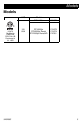
Models Models VAC 110474 Certified to CAN/CSA C22.2 No.
Warnings Warnings The following warnings are for the setup, use, grounding, maintenance, and repair of this equipment. The exclamation point symbol alerts you to a general warning and the hazard symbols refer to procedure-specific risks. When these symbols appear in the body of this manual or on warning labels, refer back to these Warnings. Product-specific hazard symbols and warnings not covered in this section may appear throughout the body of this manual where applicable.
Warnings FIRE AND EXPLOSION HAZARD Flammable fumes, such as solvent and paint fumes, in work area can ignite or explode. To help prevent fire and explosion: • Do not spray or clean with flammable materials. Use water-based materials only. • Use equipment only in well ventilated area. • Sprayer generates sparks. When flammable liquids are used near the sprayer, keep sprayer at least 20 feet (6.1 meters) away from explosive vapors. • Keep work area free of debris, including solvent, rags and gasoline.
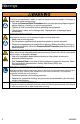
Warnings PRESSURIZED EQUIPMENT HAZARD Fluid from the equipment, leaks, or ruptured components can splash in the eyes or on skin and cause serious injury. • Follow the Pressure Relief Procedure when you stop spraying/dispensing and before cleaning, checking, or servicing equipment. • Tighten all fluid connections before operating the equipment. • Check hoses, tubes, and couplings daily. Replace worn or damaged parts immediately.
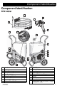
Component Identification Component Identification RTX1400si P W S R Y A E N M B C H J K F G D ti27337a A B C D E F G H J Handle Toolbox Power Cord Pump Access Panel RotoFlex™ II Pump Pump Hose Outlet Air Hose Outlet Material Flow Gauge Material Flow Control 3A3258C K M N P R S W Y ON/OFF Switch Material Hopper Burp Guard Material/Air Hose Material Thickness Gauge Nozzle Gun Air control valve Model/Serial Tag (Not shown, located on bottom of unit.
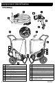
Component Identification RTX2000pi P W S R Y X A N M B C H J K F G D A B C D E F G H J K 8 Handle Toolbox Power Cord Pump Access Panel RotoFlex™ II Pump Pump Hose Outlet Air Hose Outlet Material Flow Gauge Material Flow Control ON/OFF Switch ti27338a M N P R S W X Y Material Hopper Burp Guard Material/Air Hose Material Thickness Gauge Nozzle & retaining ring Gun Prime Valve Air control valve Model/Serial Tag (Not shown, located on bottom of unit.
Preparation Preparation Pressure Relief Procedure 3. On the RTX2000pi, open air control valve. Follow the Pressure Relief Procedure whenever you see this symbol. This equipment stays pressurized until pressure is manually relieved. To help prevent serious injury from pressurized fluid or splashed fluid follow the Pressure Relief Procedure whenever sprayer is stopped and before sprayer is cleaned or checked, and before equipment is serviced. 1. ti27341a 4. Open gun prime valve.
Preparation NOTE: Lighter gauge or longer extension cords may reduce sprayer performance. Auxiliary Air Compressor Do not use an auxiliary air compressor with this spray system. Generator Requirements 3500 W (3.5 kW) minimum. Hose Size and Length The system comes with a 25 ft (7.6m) hose set consisting of a 3/4 in. ID RTX1400si/1 in. ID RTX2000pi material hose and a 3/8 in-ID air hose. Do not use more than 25 ft (7.6 m) of material hose. Soft Start/Smart Start™ System (RTX2000pi only) “Smart” vs.
Setup Setup 4. Connect material hose to gun. NOTICE • • Do not store sprayer under pressure. • When operating a RTS1400SI and you are going to stop spraying for more than five minutes turn sprayer OFF to prevent shortened pump life. 1. Connect air hose and material hose to sprayer air and material hose outlets. Do not allow material to dry inside pump, hoses, gun or spray system. ti27344a 5. Make sure burp guard is installed. Before adding material to the hopper, install the burp guard.
Setup 7. Pour one gallon (four liters) of water into the material hopper. NOTICE 10. Point gun into waste bucket and pull trigger to pump water through the system. Continue to trigger gun until material hopper is empty. To prevent pump damage, before adding material or starting unit in cold weather, run warm water through the pump. ti27381a 11. Add pre-mixed texture mix to material hopper. See Mixing Material, page 13. ti27346a 8. Turn ON/OFF switch to ON position. ti27380a 9.
Mixing Material Mixing Material NOTE: Correct material mixture is essential. The pump will not operate if the mixture is too thick. • Mix the material in a separate container before pouring it into hopper. • Use Material Thickness Gauge to determine if mixture is thin enough to spray. • The Material Thickness Gauge will only determine if the material is thin enough to pass through the pump. For some applications or for higher speed spraying, your mixture may need to be thinner.
Mixing Material NOTE: For an accurate test, be sure gauge is completely dry and clean every time it is used. 6. If the ball does not sink completely into the mixture within 10 seconds, add more water, agitate and try test again. 5. 7. Once material is mixed pour material into the sprayer hopper. See Operation, page 15 for nozzle selection and sprayer adjustments. Observe the ball on the material.
Operation Operation Texture Spraying Recommended Nozzle Selection Charts RTX1400si Application Nozzle Size2 Air Volume1 6 mm, white medium to high (fine to medium) 8 mm, gray (coarse) Orange peel 4 mm, beige, medium to high 6 mm, white Simulated Acoustic 1Control air volume with gun air valve. Application Nozzle Size2 Air Volume1 Splatter coat 6 mm, white 8 mm, gray low to medium Knockdown 6 mm, white 8 mm, gray 12 mm, black low 2For more material volume try a larger nozzle.
Operation + Closing air valve decreases air flow through gun, which increases texture material flow through pump. To achieve uniform spray pattern, adjust air valve and flow adjustment nut on gun. If you do not achieve the desired pattern, change nozzles, see Recommended Nozzle Selection Charts, page 15. To Get Less Material • Point gun away from surface you are spraying when you first pull trigger.
Shutdown and Cleanup Shutdown and Cleanup NOTE: Keep pump and hose clean when switching between simulated acoustic, knockdown and orange peel applications. A dirty pump can release particles of texture into the finish. • To increase pump life, life turn power OFF when not spraying. • Before removing material hose, perform Pressure Relief Procedure, page 9. Make certain there is no material in the hose.
Shutdown and Cleanup 6. Spray inside material hopper to circulate water through gun and hose. While circulating water, use gun to clean material hopper. ti27340a ti27339a 10. Open gun air valve. Perform pressure relief procedure, Pressure Relief Procedure, page 9. 7. Partially open gun air valve to use air to achieve better cleaning results. Air hose fittings can get hot. Allow sprayer to cool down 15 minutes before removing air hose.
Shutdown and Cleanup 3. Plug opening on bottom of material hopper with your hand. NOTICE Water or material remaining in unit when temperatures are below freezing can damage motor and/or delay pump startup. Do not allow unit to freeze. To ensure water and material are completely drained out of unit: ti27388a 4. 5. Take hopper to cleaning area for cleaning. After cleaning material hopper, position it on sprayer handle first. 1. Remove material hose from sprayer. 2. Remove pump hose from sprayer.
Maintenance Maintenance Routine maintenance is important to ensure proper operation of your sprayer. Maintenance includes performing routine actions which keep your sprayer in operation and prevent trouble in the future. Activity Interval Inspect motor shield vents for blockage. Daily or each time you spray Every 1000 gallons (3785 Check sprayer stall (RTX2000pi only). With sprayer gun NOT triggered, sprayer motor should stall liters) and not restart until gun is triggered again.
Troubleshooting Troubleshooting 1. Follow Pressure Relief Procedure, page 9, before checking or repairing. Problem Sprayer won’t run Pump won’t pump material Material runs out of bottom of sprayer 3A3258C 2. Check all possible problems and causes before disassembling the unit. Cause Solution Power switch not on Turn switch on. No power at wall outlet Check outlet by plugging in another appliance. If appliance does not work, try another outlet.
Troubleshooting Problem No air from compressor Speed of application slow or slower Intermittent flow/sputtering Cause Solution Gun air valve closed Open gun air valve. Low voltage Check extension cord length and gauge. Replace if different than recommended. Refer to Grounding and Electrical Requirements, page 9. Gun needle plugged Clean needle and retry. Worn compressor Replace compressor. Contact a qualified Graco Service Center.
Troubleshooting Problem Cause Power switch is on and sprayer Air valve on gun is closed or is plugged in, but motor does not open enough. not run, and pump does not Motor or control is damaged. cycle. 3A3258C Open air valve. Take sprayer to Graco authorized service center. Electric outlet is not providing power. Try a different outlet or plug in something that you know is working to test outlet. Reset building circuit breaker or replace fuse. Extension cord is damaged. Replace extension cord.
Troubleshooting Problem Sprayer cycles ON and OFF when trigger is released. or Sprayer cycles ON and OFF when gun is triggered. 24 Cause Solution Pressure switch is damaged. Replace pressure switch. Compressed air system leak. Locate leak; check gun, twin line hose, or internal system. Reseal leaky fitting or replace hose. Flow switch is stuck. Replace flow switch. Check valve is damaged. Replace check valve.
RTX1400si Sprayer RTX1400si Sprayer Ref. Torque Ref. Torque 1 15-20 in-lb (1.7 - 2.3 N•m) 5 27-32 in-lb (3.1 - 3.6 N•m) 2 75-95 in-lb (8.5 - 10.7 N•m) 6 90-110 in-lb (10.2 - 12.4 N•m) 3 50-70 in-lb (5.6 - 7.9 N•m) 8 4 40-50 in-lb (4.5 - 5.6 N•m) 65-85 in-lb (7.3 - 9.
RTX1400si Sprayer RTX1400si Sprayer (cont’d) Ref. Torque Ref. Torque 1 15-20 in-lb (1.7 - 2.3 N•m) 5 27-32 in-lb (3.1 - 3.6 N•m) 2 75-95 in-lb (8.5 - 10.7 N•m) 6 90-110 in-lb (10.2 - 12.4 N•m) 3 50-70 in-lb (5.6 - 7.9 N•m) 8 4 40-50 in-lb (4.5 - 5.7 N•m) 65-85 in-lb (7.3 - 9.6 N•m) then back off 1/4 turn 21 3 29 60 80 2 16 8 26 See page 32.
RTX1400si Sprayer RTX1400si Sprayer Parts List Ref. Part 1 2 3 4 5 6 7 8 9 10 17H407 15J600 15H069 17H404 17K497 277319 15J672 15J671 110755 17K546 11 12 13 14 15 112612 17H418 17K511 102313 288336 16 19 21 22 288623 120660 15H910 15C090 23 25 26 27 29 30 31 32 35 36 38 40 42 43 24S107 17H410 105240 113981 117630 117633 120771 17H490 120236 120731 289591 16M501 15J862 15D561 3A3258C Description Qty.
RTX2000pi Sprayer RTX2000pi Sprayer Ref. Torque Ref. Torque 1 15-20 in-lb (1.7 - 2.3 N•m) 5 27-32 in-lb (3.1 - 3.6 N•m) 2 75-95 in-lb (8.5 - 10.7 N•m) 6 90-110 in-lb (10.2 - 12.4 N•m) 3 50-70 in-lb (5.6 - 7.9 N•m) 8 4 40-50 in-lb (4.5 - 5.7 N•m) 65-85 in-lb (7.3 - 9.
RTX2000pi Sprayer RTX2000pi Sprayer (cont’d) Ref. Torque Ref. Torque 1 15-20 in-lb (1.7 - 2.3 N•m) 6 90-110 in-lb (10.2 - 12.4 N•m) 2 75-95 in-lb (8.5 - 10.7 N•m) 7 9-11 in-lb (1- 1.2 N•m) 3 50-70 in-lb (5.6 - 7.9 N•m) 8 4 40-50 in-lb (4.5 - 5.7 N•m) 9 5 27-32 in-lb (3.1 - 3.6 N•m) 65-85 in-lb (7.3 - 9.6 N•m) then back off 1/4 turn 120-130 in-lb (13.6 - 14.7 N•m) 3 21 1 73 2 29 8 49 80 27 26 80 8 122 67 100 16 See page 32.
RTX2000pi Sprayer RTX2000pi Sprayer Parts List Ref.
RTX2000pi Sprayer Ref. Part Description 104 105 106 107 108 109 118 119 121 122 123 124 100403 110198 17J393 111800 110996 102478 17L028 17L120 17L386 15E332 PLUG, pipe COUPLER, line, air FITTING, tube, straight SCREW, cap hex, hd NUT, hex, flange head TUBE, air, 0.375 STRAP, tie TUBE, air LABEL, pi models GROMMET, edge FITTING LABEL, Home Depot Tool Rental 17L017 Qty.
Compressor Parts Compressor Parts Ref. 1 2 Torque Ref. 18-22 ft-lb (24.4 - 29.8 N•m) 50-65 in-lb (5.7 - 7.3 N•m) 5 120-140 in-lb (13.6 - 15.8 N•m) Finger tighten cap screw in position 4 first then torque cap screws in the sequence illustrated. 6 190-230 in-lb (21.5 - 26 N•m) 3 Piston retaining bolt & crankshaft bolts must torqued before head bolts (30) are torqued. 4 60-72 in-lb (6.8 - 8.
Compressor Parts Compressor Parts List Ref.
Wiring Diagram Wiring Diagram RTX1400si POWER CORD GREEN WHITE BLACK GREEN MOTOR BLACK SWITCH ti27930a RTX2000pi YELLOW MOTOR ORANGE 49 REF 11 ORANGE VIOLET AC NEUTRAL TRIAC GATE BROWN TRIAC A1 BLUE WHITE MOTOR GRAY SOLENOID BLACK RED ORANGE ORANGE PRIME SWITCH PRESSURE SWITCH VIOLET VIOLET VIOLET WHITE GREEN GREEN BROWN WHITE GRAY ORANGE FLOW SWITCH VIOLET RED BLUE BLACK BLACK TRIAC IS PART OF PC BOARD ASSEMBLY AC HOT VIOLET BLACK ti27929a HOUR METER Hour meter
Technical Specifications Technical Specifications Sprayer Material Hopper Capacity RTX1400si RTX2000pi Maximum Delivery with Texture RTX1400si RTX2000pi Maximum Fluid Working Pressure Maximum Air Working Pressure Compressor Air Displacement Compressor Specifications Electric Motor Power Cord Generator Minimum Power Requirements Dimensions Height RTX1400si RTX2000pi Length RTX1400si RTX2000pi Width RTX1400si RTX2000pi Weight (includes hose and gun) RTX1400si RTX2000pi Weight (gun) RTX1400si RTX2000pi US Me
Technical Specifications US Materials of Construction Wetted materials on all models Metric brass, aluminum, plastic, stainless steel, plated carbon steel, elastomer Notes * Startup pressures and displacement per cycle may vary based on suction condition, discharge head, air pressure, and fluid type. ** Sound pressure measured 3 feet (1 meter) from equipment while spraying. Sound power measured per ISO-9614. Pump damage will occur if water-based fluid freezes in pump.
Graco Standard Warranty Graco Standard Warranty Graco warrants all equipment referenced in this document which is manufactured by Graco and bearing its name to be free from defects in material and workmanship on the date of sale to the original purchaser for use. With the exception of any special, extended, or limited warranty published by Graco, Graco will, for a period of twelve months from the date of sale, repair or replace any part of the equipment determined by Graco to be defective.
Graco Information For the latest information about Graco products, visit www.graco.com. For patent information, see www.graco.com/patents. TO PLACE AN ORDER, contact your Graco distributor or call 1-800-690-2894 to identify the nearest distributor. All written and visual data contained in this document reflects the latest product information available at the time of publication. Graco reserves the right to make changes at any time without notice. Original instructions. This manual contains English.