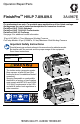
Operation/Repair/Parts FinishPro™ HVLP 7.0/9.0/9.5 3A4967E EN For professional use only. For portable spray applications of fine finish coatings. Not approved for use in explosive atmospheres or hazardous locations. FinishPro HVLP 7.0/9.0 Standard FinishPro HVLP 7.0/9.0/9.5 ProContractor FinishPro HVLP 9.5 ProComp See page 3 for additional model information 10 psi (0.07 MPa, 0.7 bar) Maximum Working Pressure ProComp Models: 50 psi (0.35MPa, 3.
Table of Contents Table of Contents Models . . . . . . . . . . . . . . . . . . . . . . . . . . . . . . . . . . . . . . . . . . . . . 3 Key Features . . . . . . . . . . . . . . . . . . . . . . . . . . . . . . . . . . . . . 3 Warnings . . . . . . . . . . . . . . . . . . . . . . . . . . . . . . . . . . . . . . . . . . . 4 Know Your Sprayer . . . . . . . . . . . . . . . . . . . . . . . . . . . . . . . . . . . 7 Standard Models . . . . . . . . . . . . . . . . . . . . . . . . . . . . . . . . . .
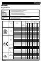
Models Models Key Features SmartStart Available only on ProContractor and ProComp models FlexLiner System Not available on all models • • • • • • Allows user to adjust sprayer performance to match application needs. Use at lowest setting that provides desired finish. Reduces heat buildup and job site noise. • • • Allows user to spray gun at any angle without cup adjustment. Reduces cleaning time with no siphon tube and disposable liner. Quick change cup connection.
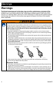
Warnings Warnings The following warnings are for the setup, use, grounding, maintenance, and repair of this equipment. The exclamation point symbol alerts you to a general warning and the hazard symbols refer to procedure-specific risks. When these symbols appear in the body of this manual or on warning labels, refer back to these Warnings. Product-specific hazard symbols and warnings not covered in this section may appear throughout the body of this manual where applicable.
Warnings FIRE AND EXPLOSION HAZARD Flammable fumes, such as solvent and paint fumes, in work area can ignite or explode. To help prevent fire and explosion: • Do not spray flammable or combustible materials near an open flame or sources of ignition such as cigarettes, motors, electrical equipment, and plastic drop cloths (potential static sparking). • Turbine motor generates sparks.
Warnings EQUIPMENT MISUSE HAZARD Misuse can cause death or serious injury. • Always wear appropriate gloves, eye protection, and a respirator or mask when painting. • Do not operate or spray near children. Keep children away from equipment at all times. • Do not overreach or stand on an unstable support. Keep effective footing and balance at all times. • Stay alert and watch what you are doing. • Do not operate the unit when fatigued or under the influence of drugs or alcohol.
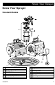
Know Your Sprayer Know Your Sprayer Standard Models A D Q C H E F G K J L M P N ti30623a A C D E F G H Edge II Spray Gun Spray Gun Tubing FlexLiner System ON/OFF Switch TurboControl (select models) Resettable Circuit Breaker Sprayer Handle 3A4967E J K L M N P Q Turbine Air Filter Air Outlet Motor Air Filter Power Cord Sprayer Air Hose Quick Connect Material Strainer 7
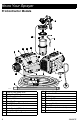
Know Your Sprayer ProContractor Models A D G F H J E C K M L O N P Q U S R T ti30754a A C D E F G H J K L 8 Edge II Plus Spray Gun Spray Gun Tubing FlexLiner System Material Strainer Fluid Set Storage ON/OFF/SmartStart Switch TurboControl TurboControl LED Indicator Spray Gun Holder Resettable Circuit Breaker M N O P Q R S T U Sprayer Handle Turbine Air Filter Air Outlet Motor Air Filter Power Cord Sprayer Air Hose Quick Connect Whip Hose (select models) Air Valve 3A4967E
Know Your Sprayer ProComp Models V W G U X P Q D T J C E B R A S F M H L K N ti30891a A B C D E F G H J K L Air Outlet ON/OFF/SmartStart Switch Fluid Set Storage Sprayer Handle Turbine Air Filter Motor Air Filter Edge II Plus Spray Gun Power Cord Resettable Circuit Breaker Quick Connect Air Valve 3A4967E M N P Q R S T U V W X Sprayer Air Hose Whip Hose Spray Gun Holder TurboControl TurboControl LED Indicator Compressor Outlet Compressor ON/OFF Switch Remote Cup, 2-qt Gun Air Hose, 5-ft R
Pressure Relief Procedure Pressure Relief Procedure Follow the Pressure Relief Procedure whenever you see this symbol. If using a FlexLiner System: 4. Disconnect tubing from gun to relieve pressure in the cup. The spray gun cup is pressurized. To reduce the risk of splashing from pressurized fluid, always follow the Pressure Relief Procedure before removing cup. 1. Turn the ON/OFF switch to OFF position. Standard Models: ti30627a If using a ProComp remote cup: 5.
Setup Setup When unpacking sprayer for the first time or after long term storage, perform setup procedure. 1. Connect air hose to sprayer. Hand tighten. 2. If using a ProComp Model with remote cup: 3. Connect gun air hose (V) to end of sprayer are hose (M). ti30759a 4. V Connect power cord to sprayer power connection. Plug sprayer power cord into grounded outlet. M ti30894a NOTICE For units with a whip hose, do not connect whip hose directly to sprayer. Connect whip hose to gun end .
Setup Fluid and Work Piece Preparation 12 • Strain fluids before spraying. This includes colors, reducers and hardeners. • Use a slower drying reducer or thinner to compensate for the faster drying time caused by the warm air of the turbine. Do not over reduce. • Sprayer performance varies with the viscosity of the material sprayed and the length of the hose. To prevent pressure drop, use hose supplied with sprayer. • Most material manufacturers provide recommendations for their materials.
Startup Startup Fill FlexLiner System 1. 2. Disconnect gun from FlexLiner System. Loosen ring from cup. Remove cover and ring from cup. Verify FlexLiner remains in cup upon removal of cover and ring. ti30706a ti30707a 3. Fill FlexLiner with material to “MAX FILL” line. Clean threads and sealing surfaces of FlexLiner System.
Startup 4. Install cover and ring onto cup. Tighten ring securely. Fill Remote Cup (ProComp Models only) 1. Fill remote cup 3/4 full and install cover. NOTICE Only hand-tighten remote cup cover. Excessive tightening may damage cover gasket. ti30709a 5. Connect FlexLiner System to gun. 3/4 ti30681a 6. Connect air hose to inlet fitting of gun. ti30683a 7. 14 You are now ready to spray. Reference Startup, page 16, and HVLP Edge II gun manual, provided with sprayer, for spraying instructions.
Startup 2. Connect clear air hose to compressor outlet and remote cup air inlet. 4. Connect air hose (V) to inlet fitting of gun. ti30898a V NOTICE If the remote cup is accidentally tipped over or held at too great of an angle, fluid may leak into air regulator and cause damage. Take precautions to avoid this. If fluid gets into regulator, clean immediately. 5. You are now ready to spray. Reference Startup, page 16, and HVLP Edge II gun manual, provided with sprayer, for spraying instructions.
Startup Startup TurboControl allows for performance adjustment of the sprayer. To reduce over-spray, always start at lowest setting and increase to the minimum setting required to provide the desired finish. 1. Turn TurboControl to lowest setting. If using FlexLiner System: 3. Point gun into a waste area. Evacuate air from FlexLiner System by holding gun vertically and pull trigger open until a continuous spray pattern is observed. NOTE: Tilt gun back and forth to help in evacuation of air.
Cup Over Installation Cup Over Installation 1. Perform Pressure Relief Procedure, page 10. 2. Disconnect gun from FlexLiner system. Loosen nut on backside of gun. Do not remove nut. Pull nozzle housing assembly out just far enough to allow rotation. Rotate nozzle housing assembly 180° so it faces upward. 3. Loosen nut on backside of gun. Do not remove nut. Pull nozzle housing assembly out just far enough to allow rotation. Rotate nozzle housing assembly 180° so it faces upward.
Cup Over Installation 4. Press nozzle housing assembly in, making sure the hole and pin are aligned and housing can no longer rotate. 5. Torque nut to 140-150 in-lb (15.8-16.9 N•m). 6. Reconnect Flexliner system.
How to Spray How to Spray • The turbine motor generates sparks. These sparks can ignite flammable fumes. • Keep sprayer in a well ventilated area. • Keep sprayer at least 20 feet (6m) from spray area. Use additional hose if necessary. Take a few moments prior to spraying and review these simple tips to ensure your spraying project is a success. Spray Techniques Use a piece of scrap cardboard to practice spraying techniques before spraying the work piece.
How to Spray Aiming Gun Refilling FlexLiner Aim center of spray gun at bottom edge of previous stroke, overlapping each stroke by half. 1. Perform Pressure Relief Procedure, page 10. 2. Reference Fill FlexLiner System, page 13. Refilling Remote Cup 1. Perform Pressure Relief Procedure, page 10 2. Reference Fill Remote Cup (ProComp Models only), page 14. ti30764a If sprayer does not spray, reference Troubleshooting, page 27.
Cleanup Cleanup Cleaning your sprayer and gun after every job is important. Proper care and maintenance results in optimal sprayer performance. 1. Perform Pressure Relief Procedure, page 10. 2. Unplug power cord from power outlet. 3. Remove turbine and motor air filters. Cleaning Filters Cleaning the filters with flammable solvents may cause the equipment to ignite or explode. Do not use flammable solvents, such as lacquer thinner, to clean the filters.
Cleanup Cleaning FlexLiner System 3. NOTICE Solvents, such as lacquer thinner, can damage parts of the FlexLiner System. Do NOT immerse parts of the FlexLiner System in solvent. 1. Perform Pressure Relief Procedure, page 10. 2. Disconnect gun from FlexLiner system. Loosen ring (1) from cup (5). Remove ring (1) and cover (2) from cup. Verify FlexLiner remains in cup upon removal of cover and ring. 1 2a 2 3 4 5 ti30775a 4. Return excess fluid to original container.
Cleanup 5. It is recommended to dispose of the used FlexLiner (4) and install a new one. If reusing, clean by wiping all excess fluid from FlexLiner (4). 7. Fill the FlexLiner (4) approximately half-full with cleaning fluid (warm water or appropriate solvent). 8. Remove and clean material strainer (3) by flushing with cleaning fluid. Re-install material strainer (3). ti30777a 9. Install cover (2) and ring (1) onto cup (5).
Cleanup 10. Cover cup fitting (2a) with a rag, shake the entire FlexLiner System for a minimum of ten seconds. ti30779a 11. Wipe clean and dry all components of FlexLiner System. Properly dispose of cleaning fluid. ti30901a ti30780a 3. Wipe excess fluid from remote cup and cover. 4. Fill remote cup quarter-full with cleaning fluid (warm water or appropriate solvent). 5. Install cover. 6. Cover cup fitting with rag, shake remote cup assembly for a minimum of ten seconds.
Cleanup 3. Cleaning HVLP Edge II Gun Move trigger slide from SPRAY position (A) to NEEDLE REMOVAL position (B). NOTICE Solvents, such as lacquer thinner, can damage parts of the HVLP Edge II gun. Do NOT immerse parts of the HVLP Edge II gun in solvent. 1. Remove retaining ring and air cap. 2. Trigger the gun and remove fluid nozzle from gun. SPRAY Position NOTE: Edge II Plus guns contain air cap guide and spring held in place by fluid nozzle.
Cleanup 5. Wipe or flush fluid from nozzle and needle. If necessary, clean retaining ring, air cap, air cap guide, and spring. NOTICE Do not use metal tools to clean the fluid nozzle or air cap holes as this may scratch them, causing fluid leaks and a distorted spray pattern. 6. Using a squeeze bottle, flush cleaning fluid through the gun. Hold the gun upside down, pull the trigger, and dispense cleaning fluid into the cup connection. ti30853a 26 7.
Troubleshooting Troubleshooting 1. Follow ProComp Models, page 9, before checking or repairing. Problem Sprayer not starting 2. Check all possible problems and causes before disassembling the unit. Cause No Power What to Do Check electrical outlet for power. Cycle ON/OFF switch. Check that correct power cord is used and plugged in. Check circuit breaker. Push to reset.
Troubleshooting Problem Poor atomization Circuit breaker trips Cause What to Do Dirty gun Clean gun. See Cleaning HVLP Edge II Gun, page 25. Dirty air filters Clean turbine and motor air filters. Replace as necessary. See Cleaning Filters, page 21. Extension cord too long Extension cord must be a 3-wire, 12 AWG (2.5mm2) minimum, 50 ft (15 m) maximum length.
Troubleshooting Problem FlexLiner does not collapse or collapses slowly Cause What to Do Dirty sealing surfaces Remove ring, clean sealing surfaces, securely install ring. See Fill FlexLiner System, page 13. Incorrect or no air cap installed on gun Verify Edge II air cap is installed. Air cap is loose Edge II: Verify retaining ring is fully installed. Edge II Plus: Verify retaining ring is installed to a position that does not result in a loose air cap.
Parts Parts Ref. Standard Models Torque 1 110-115 in-lb (12.5 - 13.0 N•m) 2 20-25 in-lb (2.5 - 3.0 N•m) 3 15-20 in-lb (1.7 - 2.3 N•m) 4 10-15 in-lb (1.1 - 1.7 N•m) 5 35-40 in-lb (4.0 - 4.
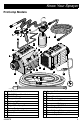
Parts List - Standard Models Parts List - Standard Models Ref. Part 1 2 3 4 5 6 7 8 9 10 11 12 13 14 15 16 17 18 19 20 17R054 129531 113817 100057 111040 Description BOX, bottom, painted SCREW, cap hex hd BUMPER SCREW, cap, hex hd NUT, lock, insert, nylock, 5/16 125135 WASHER, flat 129443 NUT, coupler GASKET, turbine 15W153 7.0 Standard 15W152 9.0 Standard SPACER, back, turbine 17N374 7.0 Standard 17N376 9.0 Standard 194094 PLATE, turbine SPACER, front, turbine 17N373 7.0 Standard 17N375 9.
Parts Parts Ref. ProContractor Models 3 Torque 1 110-115 in-lb (12.5 - 13.0 N•m) 2 20-25 in-lb (2.5 - 3.0 N•m) 3 15-20 in-lb (1.7 - 2.3 N•m) 4 10-15 in-lb (1.1 - 1.7 N•m) 5 35-40 in-lb (4.0 - 4.
Parts List - ProContractor Models Parts List - ProContractor Models Ref.Part 1 2 3 4 5 6 7 8 17R057 129604 113817 100057 111040 125135 129443 Description BOX, bottom, painted GROMMET, rubber BUMPER SCREW, cap, hex hd NUT, lock, insert, nylock, 5/16 WASHER, flat NUT, coupler GASKET, turbine 15W153 7.0 ProContractor 15W152 9.0 ProContractor 192788 9.5 ProContractor 9 SPACER, back, turbine 17N374 7.0 ProContractor 17N376 9.0 ProContractor 10 194094 PLATE, turbine 11 SPACER, front, turbine 17N373 7.
Parts Parts Ref. ProComp Models 3 Torque 1 110-115 in-lb (12.5 - 13.0 N•m) 2 20-24 in-lb (2.5 - 3.0 N•m) 3 15-20 in-lb (1.7 - 2.3 N•m) 4 10-15 in-lb (1.1 - 1.7 N•m) 5 35-40 in-lb (4.0 - 4.5 N•m) 6 5-8 in-lb (0.5 - 0.9 N•m) 7 20-23 ft-lb (28.0 - 31.
Parts List - ProComp Models Parts List - ProComp Models Ref.
Parts - Power Cords & Accessories Parts - Power Cords & Accessories 10 17P654 17P481 17P483 6 7 1 18 17 16 8 14 9 19 15 11 2 3 20 21 4 5 22 ti30844a 36 3A4967E
Parts List - Power Cords & Accessories Parts List - Power Cords & Accessories 17T237 Ref.
Wiring Diagrams (Standard) Wiring Diagrams (Standard) 120V WIRING DIAGRAM BLACK POWER INLET 3 GROUND L 5 N 1 G GREEN / YELLOW BLACK TURBINE BK W WHITE WHITE CONTROL BOARD CIRCUIT BREAKER 6 4 2 BLACK POTENTIOMETER BLACK 8 SWITCH 3 2 6 5 7 230V WIRING DIAGRAM BROWN BLUE POWER INLET N L 3 GROUND G BK TURBINE 6 GREEN / YELLOW 1 W BROWN 4 WHITE BLUE BROWN CONTROL BOARD BLACK CIRCUIT BREAKER 7 5 POTENTIOMETER ti30765a 38 BLUE BROWN 9 SWITCH 3 2 6 5 2 BROWN B
Wiring Diagrams (Standard) Wiring Diagrams (Standard) 120V UK WIRING DIAGRAM (Model 17T980) 1 BROWN BLUE POWER INLET GROUND 2 TURBINE N L 3 G BK 6 GREEN W 4 WHITE BLACK 7 BLUE N1 N FILTER CIRCUIT BREAKER P BROWN P1 SWITCH ti32193a 3A4967E BLUE BROWN BROWN 3 2 6 5 8 BLUE 39
Wiring Diagrams (ProContractor) Wiring Diagrams (ProContractor) 120V WIRING DIAGRAM TURBINE BLACK BK W BARRIER WALL GROUND GREEN / YELLOW WHITE 4 BLACK L 1 6 N 7 G 2 WHITE YELLOW THERMISTOR SWITCH POWER INLET 3 CIRCUIT BREAKER BLACK 5 PURPLE RIBBON GRAY GREEN CONTROL BOARD 9 POTENTIOMETER BLACK POTENTIOMETER HARNESS 8 LED PURPLE GRAY GREEN RIBBON 120V UK & 230V WIRING DIAGRAM BARRIER WALL TURBINE BLACK BK W WHITE THERMISTOR YELLOW SWITCH GROUND POWER INLET 2 BROWN L G
Wiring Diagrams (ProComp) Wiring Diagrams (ProComp) 3A4967E 41
Technical Specifications Technical Specifications FinishPro HVLP 7.0/9.0 Standard US FinishPro 7.0 Maximum Amperage Watts Electrical Power Requirement Maximum Hose Length Sprayer Weight Total Weight Noise* (dBa) Sound pressure Sound power FinishPro 9.0 Maximum Amperage Watts Electrical Power Requirement Maximum Hose Length Sprayer Weight Total Weight Noise* (dBa) Sound pressure Sound power Materials of Construction Wetted materials on all models Metric 11.
Technical Specifications FinishPro HVLP 7.0/9.0/9.5 ProContractor US FinishPro 7.0 Maximum Amperage Watts Electrical Power Requirement Maximum Hose Length Sprayer Weight Total Weight Noise* (dBa) Sound pressure Sound power FinishPro 9.0 Maximum Amperage Watts Electrical Power Requirement Maximum Hose Length Sprayer Weight Total Weight Noise* (dBa) Sound pressure Sound power FinishPro 9.
Technical Specifications FinishPro HVLP 9.5 ProComp US FinishPro 9.5 Maximum Amperage Watts Electrical Power Requirement Maximum Hose Length Sprayer Weight Total Weight Noise* (dBa) Sound pressure Sound power Materials of Construction Wetted materials on all models Metric 15.0 9,0 1800 120 VAC, 50/60 Hz,15A 220-240 VAC, 50Hz,10A 60 ft 18,3 m 30 lb 13,6 kg 46 lb 20,9 kg 83.4 dBa 96.
Notes Notes 3A4967E 45
Graco Standard Warranty Graco Standard Warranty Graco warrants all equipment referenced in this document which is manufactured by Graco and bearing its name to be free from defects in material and workmanship on the date of sale to the original purchaser for use. With the exception of any special, extended, or limited warranty published by Graco, Graco will, for a period of twelve months from the date of sale, repair or replace any part of the equipment determined by Graco to be defective.
Graco Information Graco Information For the latest information about Graco products, visit www.graco.com. For patent information, see www.graco.com/patents. TO PLACE AN ORDER, contact your Graco distributor or call 1-800-690-2894 to identify the nearest distributor.
All written and visual data contained in this document reflects the latest product information available at the time of publication. Graco reserves the right to make changes at any time without notice. Original instructions. This manual contains English. MM 3A4967 Graco Headquarters: Minneapolis International Offices: Belgium, China, Japan, Korea GRACO INC. AND SUBSIDIARIES • P.O. BOX 1441 • MINNEAPOLIS MN 55440-1441 • USA Copyright 2014, Graco Inc.