Operation, Repair, Parts SaniSpray HP™ 130 Cart Airless Sprayer 3A7656A EN For portable spraying of water-based disinfectants approved for spray application only. Not for applying architectural paints and coatings. Not approved for use in explosive atmospheres or hazardous (classified) locations. For professional use only. Important Safety Instructions Read all warnings and instructions in this manual, in related manuals, and on the unit before using the equipment.
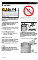
Contents Contents Important User Information . . . . . . . . . . . . . . . . . . . . . . . . . . . . . . . . . . 3 Warnings . . . . . . . . . . . . . . . . . . . . . . . . . . . . . . . . . . . . . . . . . . . . . . . . . 4 Know Your Sprayer . . . . . . . . . . . . . . . . . . . . . . . . . . . . . . . . . . . . . . . . . 8 Grounding . . . . . . . . . . . . . . . . . . . . . . . . . . . . . . . . . . . . . . . . . . . . . . . . 9 Power Requirements . . . . . . . . . . . . . . . . . . . . . . . . . . . . .
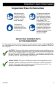
Important User Information Important User Information Before using your disinfectant sprayer, read this manual for complete instructions on proper use and safety warnings. The sprayer is designed to spray disinfectants that are water-based and clean up with water. You must also read and follow the information on the disinfectant container label and ask for a Safety Data Sheet (SDS) from your supplier.
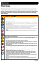
Warnings Warnings The following warnings are for the setup, use, grounding, maintenance, and repair of this equipment. The exclamation point symbol alerts you to a general warning and the hazard symbols refer to procedure-specific risks. When these symbols appear in the body of this manual or on warning labels, refer back to these Warnings. Product-specific hazard symbols and warnings not covered in this section may appear throughout the body of this manual where applicable.
Warnings WARNING FIRE AND EXPLOSION HAZARD Flammable fumes, such as disinfectants, in work area can ignite or explode. To help prevent fire and explosion: • Do not spray flammable disinfectants near an open flame or sources of ignition such as cigarettes, motors, and electrical equipment. • Disinfectants flowing through the equipment are able to result in static electricity. Static • • • • • • • • electricity creates a risk of fire or explosion in the presence of disinfectant fumes.
Warnings WARNING ELECTRIC SHOCK HAZARD This equipment must be grounded. Improper grounding, setup, or usage of the system can cause electric shock. • Turn off and disconnect power cord before servicing equipment. • Connect only to grounded electrical outlets. • Use only 3-wire extension cords. • Ensure ground prongs are intact on power and extension cords. • Do not get wet or expose to rain. Store indoors. • Wait five minutes after disconnecting power cord before servicing.
Warnings GROUNDING WARNING This product must be grounded. In the event of an electrical short circuit, grounding reduces the risk of electric shock by providing an escape wire for the electric current. This product is equipped with a cord having a grounding wire with an appropriate grounding plug. The plug must be plugged into an outlet that is properly installed and grounded in accordance with all local codes and ordinances.
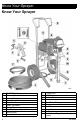
Know Your Sprayer Know Your Sprayer A B C D E F G H J K 8 ON/OFF Switch Pressure Control Knob Airless Whip Hose Prime/Spray Valve Hose Guard Spray Tip Guard Spray Tip Flex Plus Airless Spray Gun Airless Hose Power Cord L M N P R S T U V Trigger Lock Drain Tube Suction Tube Pump Fluid Outlet Fitting Hanger Inlet Strainer Finger Guard Pail Hook Model/Serial Tag, bottom of unit (not shown) 3A7656A
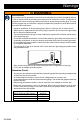
Grounding Grounding The equipment must be grounded to reduce the risk of static sparking and electric shock. An electric or static spark can cause fumes to ignite or explode. An improper ground can cause electric shock. A good ground provides an escape wire for the electric current. This sprayer is equipped with a Power Cord that has a ground wire and an appropriate grounding plug. Always ground a metal pail: connect a ground wire to the pail.
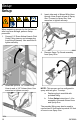
Setup Setup 3. Insert other end of Airless Whip Hose through Hose Guard at base of Spray Gun. Connect to Spray Gun. Use wrenches to tighten securely. 4. Remove Spray Tip Guard assembly from Spray Gun. When unpacking sprayer for the first time or after long term storage, perform Setup procedure. 1. 2. Connect 1/4” Graco Airless Hose to Fluid Outlet Fitting (remove red storage plug from fitting if present). Use wrenches to tighten securely.
Start Up Start Up 2. Engage the Trigger Lock. Always engage the Trigger Lock when sprayer is stopped to prevent the Spray Gun from being triggered accidentally. 3. Turn Pressure Control Knob to the lowest setting. 4. Put Drain Tube in a pail and turn Prime/Spray Valve down to PRIME position to relieve pressure. Pressure Relief Procedure Follow the Pressure Relief Procedure whenever you see this symbol. This equipment stays pressurized until pressure is manually relieved.
Start Up 5. Hold a metal part of the Spray Gun firmly to a grounded metal pail. Point Spray Gun into pail. Disengage the Trigger Lock and trigger the Spray Gun to relieve pressure. 6. Engage the Trigger Lock. 7. If you suspect the Spray Tip or Airless Hose is clogged or that pressure has not been fully relieved: a. b. c. 12 Trigger Lock Always engage the Trigger Lock when sprayer is stopped to prevent the Spray Gun from being triggered accidentally by hand or if dropped or bumped.
Start Up Flushing a New Sprayer 4. Turn Prime/Spray Valve down to PRIME position. 5. Plug power supply cord into a properly grounded electrical outlet. This sprayer arrives from the factory with a small amount of test fluid in the system. It is important that you flush this fluid from the sprayer before using it for the first time. 1. Perform Pressure Relief Procedure, page 11. 2. Make certain ON/OFF Switch is OFF. 3.
Start Up 6. 7. 8. 9. 14 Turn ON/OFF Switch to ON position. Fill Pump 1. Turn Pressure Control Knob to lowest setting. 2. Turn ON/OFF Switch to ON position. 3. Place Suction Tube in pail of disinfectant. Place Drain Tube in waste bucket. 4. Turn Pressure Control Knob to Prime/ Slow to start motor. Wait until disinfectant flows from the Drain Tube. 5. Turn ON/OFF Switch to OFF position. Turn Pressure Control Knob to Prime/Slow to start motor.
Start Up Fill Spray Gun and Airless Hose 1. Hold Spray Gun against grounded metal waste bucket. Point Spray Gun into waste bucket. a. Disengage Trigger Lock. b. Pull and hold Spray Gun trigger. c. Turn Prime/Spray Valve horizontal to SPRAY position. d. Turn ON/OFF Switch to ON position. 4. Inspect Airless Hose connections for leaks. If leaks occur, perform Pressure Relief Procedure, page 11, then tighten all fittings and repeat Start Up. If there are no leaks, continue with the next step. 5.
How to Spray How to Spray 2. Use Spray Tip (A) to align gasket and seal (B) in the Spray Tip Guard (C). 3. Insert Spray Tip into Spray Tip Guard. 4. Screw Spray Tip Guard assembly onto Spray Gun and tighten. Use only disinfectants approved for spray application. Fumes from disinfectants with alcohol active ingredients, or from other flammable disinfectants, can explode or ignite. Pump motor generates sparks.
How to Spray Starting Your Spray and Adjusting Pressure 1. Always refer to the disinfectant manufacturer’s recommendations for an acceptable spray of disinfectant. 1. Point Spray Gun towards the surface to be sprayed. 2. Confirm the Pressure Control Knob is at the lowest setting. 3. Disengage Trigger Lock. 4. Pull and hold Spray Gun trigger. 5. Slowly increase pressure using the Pressure Control Knob. Set to the minimum setting necessary to produce an acceptable spray of disinfect.
Cleanup Cleanup Cleaning the sprayer is required after each use to remove any disinfectants and residues from the sprayer. It will also help ensure a trouble free start up the next time the sprayer is used. Clean Drain Tube 3. Remove Suction Tube and Drain Tube from pail of disinfectant, wipe excess disinfectant off outside. Use only water for cleaning. Clean in a well-ventilated area. Keep a good supply of fresh air moving through the area. NOTICE Disinfectant left in sprayer will damage the sprayer.
Cleanup 5. To flush Drain Tube and Pump, turn Prime/Spray Valve down to PRIME position. 6. Turn Pressure Control Knob to Prime/Slow and turn ON/OFF Switch to ON position. Allow water to flow out of the Drain Tube into the waste bucket for 1 to 3 minutes. 3A7656A 7. Turn Pressure Control Knob to the lowest setting.
Cleanup Clean Hose and Spray Gun 10. Stop triggering Spray Gun. NOTE: Step 8 is for removing disinfectant from the Airless Hose. One 50 ft Airless Hose holds approximately 1 quart of fluid. 11. Raise Suction Tube above water level. 8. To remove disinfectant from Airless Hose: a. Hold Spray Gun against waste bucket. b. Disengage Trigger Lock. c. Pull and hold Spray Gun Trigger. d. Turn Prime/Spray Valve horizontal to SPRAY position. e.
Storage 13. Turn Prime/Spray Valve down to PRIME position. 16. Dispose of unused disinfectant and fluid in the waste bucket according to the instructions on the disinfectant container label and applicable regulations. Clean the Gun 14. Turn Pressure Control Knob to lowest setting and turn ON/OFF Switch to OFF position. Disconnect power to sprayer. 1. Remove Spray Tip and Spray Tip Guard assembly. Clean with water and a brush. 2. Wipe Spray Gun with soft cloth moistened with water.
Maintenance Maintenance Routine maintenance is important to ensure proper operation of your sprayer. Perform Pressure Relief Procedure, page 11, before performing maintenance. Activity Inspect/clean Inlet Strainer. Inspect motor shield vents for blockage. Check sprayer stall. Interval Daily or each time you spray Daily or each time you spray Every 1000 gallons (3785 liters) With Spray Gun NOT triggered, sprayer motor should stall and not restart until Spray Gun is triggered again.
Recycling and Disposal Recycling and Disposal End of Product Life • Remove motors, batteries, circuit boards, LCDs (liquid crystal displays), and other electronic components. Recycle according to applicable regulations. • Do not dispose of electronic components with household or commercial waste. • Deliver remaining product to a recycling facility. At the end of the product’s useful life, dismantle and recycle it in a responsible manner. • Perform the Pressure Relief Procedure, page 11.
Troubleshooting Troubleshooting Mechanical/Fluid Flow 1. Disconnect power cord and follow Pressure Relief Procedure, page 11, before checking or repairing. 2. Check all possible problems and causes before disassembling the unit. 844-241-9499 Problem Pump output is low What to Check If check is OK, go to next check What to Do When check is not OK, refer to this column Spray Tip worn. Follow Pressure Relief Procedure, page 11, then replace Spray Tip. Fluid supply. Refill and reprime Pump.
Troubleshooting Problem Pump output is low Motor runs but Pump does not stroke Excessive material leakage into throat packing nut Fluid is spitting from Spray Gun 3A7656A What to Check If check is OK, go to next check What to Do When check is not OK, refer to this column Pump rod damage. Replace Pump if necessary. See Parts, page 32. Low stall pressure. Turn pressure knob fully clockwise. Make sure Pressure Control Knob is properly installed to allow full clockwise position.
Troubleshooting Problem Pump is difficult to prime Sprayer operates for 5 to 10 minutes then stops 26 What to Check If check is OK, go to next check What to Do When check is not OK, refer to this column Air in Pump or hose. Check and tighten all fluid connections. Cycle Pump as slowly as possible during priming. Intake valve is leaking. Clean intake valve. Be sure ball seat is not nicked or worn and that ball seats well. Reassemble valve. Pump packings are worn. Replace Pump assembly.
Troubleshooting Electrical Symptom: Sprayer does not run, stops running, or will not shut off. 1. Perform Pressure Relief Procedure, page 11. 2. Plug sprayer into correct voltage, grounded outlet. 3. Turn the ON/OFF Switch OFF wait 30 seconds and then turn power back ON again (this ensures sprayer is in normal run mode). 4. Turn Pressure Control Knob clockwise 1/2 turn. 5. Turn the ON/OFF Switch OFF, remove the control cover then turn power back ON. Observe the status light.
Troubleshooting Problem What to Check How to check Sprayer does not shut off Control board. AND Control board status light blinks 2 times repeatedly Replace control board. See Parts, page 32. Check transducer or Sprayer does not run at all transducer connections AND Control board status light blinks 2 times repeatedly Make sure there is no pressure in the system (see Pressure Relief Procedure, page 11). Check fluid path for clogs, such as clogged Inlet Strainer.
Troubleshooting Problem What to Check How to check Sprayer does not run at all AND Control board status light blinks 5 times repeatedly Control is commanding motor to run but motor shaft does not rotate. Possibly locked rotor condition, an open connection exists between motor and control, there is a problem with motor or control board, or motor amp draw is excessive. 1.Remove Pump and try to run sprayer. If motor runs, check for locked or frozen Pump or drive train.
Troubleshooting Problem What to Check How to check 5.Perform Spin Test: Test at large 4-pin motor field connector. Disconnect fluid Pump from sprayer. Test motor by placing a jumper across pins 1 & 2. Rotate motor fan at about 2 revolutions per second. A cogging resistance to motion should be felt at the fan. The motor should be replaced if no resistance is felt. Repeat for pin combinations 1 & 3 and 2 & 3. Pin 4 (the green wire) is not used in this test. If all spin test is positive, continue to step 6.
Troubleshooting Problem What to Check Sprayer does not run at all Motor is hot or there is a fault in the motor thermal device. AND Control board status light blinks 6 times repeatedly How to check Allow sprayer to cool. If sprayer runs when cool, correct cause of overheating. Keep sprayer in cooler location with good ventilation. Make sure motor air intake is not blocked. If sprayer still does not run, replace motor. NOTE: Motor must be cooled down for the test. 1.
Parts Parts 25R793 Cart Airless Sprayer Parts List - 25R793 Cart Airless Sprayer Ref. Part Description Qty. 1 25R916 KIT, pump 1 2 25R917 KIT, motor, drive 1 3 25R918 KIT, enclosures 1 4 25R919 KIT, control assembly 1 5 240794 HOSE, 1/4 in x 50 ft 2 6 25C828 HOSE, 1/8 in x 4-1/2 ft 2 7 25R874 GUN, SaniSpray HP 2 8 25R899 KIT, suction, hoses 1 25R872* SEALS, gun, polymer (5-pack) (not shown) 26B143 EXTENSION, 15 in (not 2 shown) 32 Ref. Part Description Qty.
Wiring Diagrams Wiring Diagrams 120V/110V 3A7656A 33
Technical Specifications Technical Specifications SaniSpray HP 130 Cart Airless Sprayer Sprayer Maximum fluid working pressure Maximum Delivery Maximum Tip Size Single Gun Two Guns Fluid Outlet npsm Generator Minimum Power Requirements Dimensions Height US Metric 1000 psi 1.0 gpm 69 bar, 6.9 MPa 3.8 lpm 0.023 in 0.019 in 0.58 mm 0.48 mm 1/4 in. 4000 W 0–120V, 15 A 28.25 in. (Handle down) 71.8 cm (Handle down) 38.25 in. (Handle up) 97.2 cm (Handle up) Length 23.25 in. 59.1 cm Width 20.5 in. 52.
Graco Warranty Graco Warranty Graco warrants all equipment referenced in this document which is manufactured by Graco and bearing its name to be free of defects in material and workmanship on the date of sale by an authorized Graco distributor to the original purchaser for use. Graco will, for a period of ninety (90) days from the date of sale, send repair parts to the owner for equipment determined by Graco to be defective.
Graco Information For the latest information about Graco products, visit www.graco.com. For patent information, see www.graco.com/patents. TO PLACE AN ORDER, contact your Graco distributor or call 1-800-690-2894 to identify the nearest distributor. All written and visual data contained in this document reflects the latest product information available at the time of publication. Graco reserves the right to make changes at any time without notice. Original instructions. This manual contains English.