
User's Manual


5306520
Installation
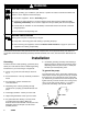
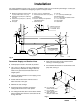
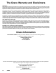
The typical installation shown in Fig. 2 is only an installation guide; it is not an actual system design. Contact your
Graco distributor for assistance in designing a system to suit your needs.
Fig. 2
01495
A
B
C
D
E
F
H
G
K
L
M
N
E
P
J
Q
C
B
R
A Maximum vertical lift, tank foot valve
to pump intake valve: 10 ft. (3 m)
B Suction line at pump: 9 in. (230 mm)
from wall
C Suction line at pump: 6 in. (150 mm)
above floor
D Vent pipe
E Pipe: 1.5 or 2 in. standard iron
F Horizontal suction line: 75 ft. (23 m)
maximum
G Stub assembly
H O.P.W. – Buckeye or equivalent
extractable suction
J Manhole cover
K Fill cap
L 4 in. (102 mm) standard pipe
M Extractor fitting
N 4 in. (102 mm) from bottom of tank
P 1.5 in. foot valve
Q Swing joints
R Gate valve
Permanent Supply and Suction Lines
D Install pumps as close to the tanks as practical.
D Use 1.5 or 2 in. (38 mm or 50 mm) standard iron
pipe and heavy malleable iron fittings. Ream the
ends of iron pipe and use thread sealant for an
airtight system.
D Use long sweeping bends for turns in piping; avoid
unnecessary turns.
D All tube ends must be clean and free of burrs.
Ream the ends of iron pipe.
D Minimize the use of fittings.
D Avoid using unions and other connections
underground and in hard to reach places.
D For underground tanks, blow out and clean all lines
before installing them. Start the connections at the
storage tank end.
D Flush and test the lines under pressure before
covering or cementing in place.
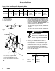
D For installation dimensions for suction lines at the
pump end, see Fig. 3.
Fig. 3
01496
B 9 in. (230 mm),
Suction line at pump
C 6 in. (150 mm),
Suction line at pump
S 20 in. (510 mm),
Between suction lines
C
C
B
B
S