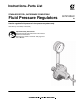
Instructions–Parts List STAINLESS STEEL, WATERBASE COMPATIBLE Fluid Pressure Regulators Used to regulate fluid pressure in low pressure systems only. Fluid Flow up to 3 GPM (11 liters/min) Important Safety Instructions Read all warnings and instructions in this manual. Save these instructions. See page 2 for Table of Contents. See page 3 for List of Models.
Table of Contents Models . . . . . . . . . . . . . . . . . . . . . . . . . . . . . . . . . . . . . . . . 3 Warnings . . . . . . . . . . . . . . . . . . . . . . . . . . . . . . . . . . . . . . 5 Installation . . . . . . . . . . . . . . . . . . . . . . . . . . . . . . . . . . . . . 6 Operation . . . . . . . . . . . . . . . . . . . . . . . . . . . . . . . . . . . . . 8 Troubleshooting . . . . . . . . . . . . . . . . . . . . . . . . . . . . . . . 11 Service . . . . . . . . . . . . . . . . . . . . . . . . . . .
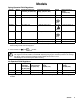
Models Spring Operated Fluid Regulators Part No. Series Maximum Fluid Inlet Pressure, psi (kPa, bar) Regulated Pressure Range, psi (kPa, bar) Gauge Gauge Pressure Range, psi (kPa, bar) 214895 H 250 (1800, 18) 5–100 (34–700, 0.3–7) No n/a 214706 H 250 (1800, 18) 5–100 (34–700, 0.3–7) Yes (see 0–100 (0–700, 0–7) below) 24A082 A 250 (1800, 18) 5–100 (34–700, 0.3–7) Yes (see 0–100 (0–700, 0–7) below) 255374 B 250 (1800, 18) 5–100 (34–700, 0.
Notes 4 307212
WARNING PRESSURIZED EQUIPMENT HAZARD Spray from the gun, hose leaks, or ruptured components can splash fluid in the eyes or on the skin and cause serious injury. Do not stop or deflect fluid leaks with your hand, body, glove, or rag. Follow the Pressure Relief Procedure on page 8 whenever you: are instructed to relieve the pressure; stop spraying; clean, check, or service the equipment; and install or clean the fluid nozzle. Tighten all the fluid connections before operating the equipment.
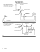
Installation FLUID SUPPLY Spring Operated Installation Models 214895, 214706, 217314, 221118, 255374, and 24A082 OUTLET BALL VALVE INLET BALL VALVE AIR FILTER & REGULATOR PIPE NIPPLES BACK PRESSURE VALVE FLUID RETURN Fig. 1 Pilot Regulator Air Supply Line Air Operated Installation Model 214980 shown FLUID REGULATOR AIR REGULATOR BYPASS VALVE INLET BALL VALVE OUTLET BALL VALVE AIR FILTER MOISTURE SEPARATOR & REGULATORS Fig.
Installation Fluid pressure regulators are used for accurate, positive control of the fluid pressure to spray guns, dispensing valves or atomizing heads. Regulators installed at circulating line take-offs or pumps are used to reduce main line pressure and maintain the desired fluid pressure to the spray gun or atomizing head. Before Installing the Fluid Regulator 1. Determine where to locate the regulator. Installing the Fluid Regulator 1.
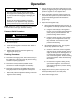
Operation CAUTION The new system must be cleaned and tested thoroughly before admitting fluid to the regulator to avoid contaminants clogging or damaging the regulator. Always use the lowest possible air and fluid pressures for your application. High pressures cause premature spray nozzle and pump wear. NOTE: Reference numbers and letters in parentheses in the text refer to the Figs. and Parts Drawing. Pressure Relief Procedure 2.
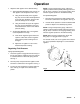
Operation 7. Adjust the fluid regulator to the desired setting. a. Spring Operated Regulators Only (see Fig. 3). The regulator can be adjusted in two ways: Using the male end (B) of the regulator key (24), turn the socket–head adjustment screw (19) fully clockwise. Verify that the pressure setting has not changed. Using the female end (A) of the regulator key (24), turn the adjustment screw (12) counterclockwise to return to the desired pressure setting. b. Air Operated Regulator Only.
Notes 10 307212
Troubleshooting WARNING To reduce the risk of serious injury whenever you are instructed to relieve pressure, always follow the Pressure Relief Procedure on page 8. Before servicing this equipment always make sure to Relieve the Pressure. Check all possible remedies in the Troubleshooting Chart before disassembling the fluid regulator. Problem Cause Solution No pressure regulation Damaged or clogged air regulator or line (214980 only) Clear obstruction in line, service regulator if necessary.
Service Service of the Air Operated Regulators WARNING To reduce the risk of serious injury whenever you are instructed to relieve pressure, always follow the Pressure Relief Procedure on page 8. 1. Shut off the pump. 2. Close the ball valve at the regulator’s air inlet. Refer to Fig. 2. 3. Release all the air and fluid pressure in the regulator and disconnect the air and fluid lines. 4. Remove the regulator from the system. 5. Remove the swivel union (23) and spring (40) from the regulator body. 6.
Service Models 214980 (shown) & 244375 29 1 Air Bleed Hole 10 1 Torque to 21–35 ft-lb (28–47 N m) 2 Torque to 21–25 ft-lb (28–34 N m) 3 Torque to 23–27 ft-lb (31–36 N m) 2 13 1 7 17 1 22 NOTE: Numbers indicate tightening sequence. Tighten evenly to 7–10 in-lb (0.8–1.1 N m), then retorque to 125 in-lb (14 N m) three times, consecutively, to compensate for diaphragm relaxation. 26 18 9 15 16 4 20 23 6 21 3 BOTTOM VIEW 5 3 2 1 4 3 6 40 Fig.
Service Service of the Spring Operated Regulators WARNING To reduce the risk of serious injury whenever you are instructed to relieve pressure, always follow the Pressure Relief Procedure on page 8. 1. Shut off the pump. 2. Close the ball valve at the regulator’s fluid inlet. See Fig. 1. 3. Release all fluid pressure in the regulator and disconnect the fluid line. 4. Remove the regulator from the system. 5. Remove the swivel union (23) and spring (40) from the regulator body. 6.
Service Models 217314 and 221118 12 7 10 1 1 1 Torque to 21–25 ft-lb (28–34 N m) 2 Torque to 21–35 ft-lb (28–47 N m) 3 Torque to 23–27 ft-lb (31–36 N m) 4 PTFE side down toward housing (6) 21 13 5 2 25 PET 22 3 18 26 4 17 Models 214895, 214706, 255374, and 24A082 15 16 9 23 3 12 6 4 20 40 10 1 21 NOTE: Numbers indicate tightening sequence. Tighten evenly to 7–10 in-lb (0.8–1.
Parts Model 214895, Series H 24 Without gauge. Includes items 1–26, 40 13 Model 214706, Series H With gauge. Includes items 1–40 17 7 22* 26* 19 14 18 12 6 11 5 *15 *16 10 *20 *21 *3 28 *9 27 Ref No. Part No. Description 1 100644 SCREW, soc hd cap; 0.25”–20 x 0.
Parts 24 Model 255374, Series A Model 24A082, Series A 13 ISO pitch thread inlet and outlet (not compatible with US standard pitch – fluid housing coated with PTFE based polymer) Includes items 1–40 17 7 22* 26* 19 14 18 12 6 11 5 *15 *16 10 *20 1 40* 4* *21 *3 23 *9 27 TI0037 Ref No. Part No. Description 1 100644 SCREW, soc hd cap; 0.25”–20 x 0.
Parts Model 217314, Series F 24 With gauge. Includes items 1–32, 40 13 Model 221118, Series E Without gauge. Includes items 1–26, 32–40 17 7 25* 22* 19 26* 14 18 32 12 Model 221118 only 39 11 6 5 *15 *16 10 *20 *21 *3 Description 1 100644 SCREW, soc hd cap; 0.25”–20 x 0.
Parts Model 214980 Series F Includes items 1–40 13 17 22* 26* 18 7 6 29 1 *15 *16 10 40* *20 4* *21 28 23 *3 *9 Ref No. Part No. Description 1 100644 SCREW, soc hd cap; 0.25”–20 x 0.
Parts Model 244375 Series B Includes items 1–41 7 26* 29 18 10 *21 6 *3 41 *9 1 *15 *16 13 *20 4* 19 17 40* 23 *22 TI1697A Ref No. Part No. Description 1 100644 SCREW, soc hd cap; 0.25”–20 x 0.
Dimensions 1.76” (44.7 mm) Model 244375: 3” (76.2 mm) All Other Models: 4.94” (125.5 mm) 1/4 npt GAUGE PORT 1.8” (46 mm) 10.25” (260 mm) 3/8 npsm female INLET 1/4 npt AIR INLET (Model 214980 only) 3.65” (93 mm) DIA.
Technical Data Category Data Maximum Fluid Inlet Pressure 250 psi (1.8 MPa, 18 bar) Regulated Fluid Pressure Range Models 217314 & 221118: 20–160 psi (0.15–1.1 MPa, 1.5–11 bar) Models 214706, 214895, 244375, 255374, & 24A082: 5–100 psi (30–700 kPa, 0.3–7.0 bar) Model 214980: 0–30 psi (0–210 kPa, 0–2 bar) Maximum Flow Capacity 3 gpm (11 liters/min) with 70 cps fluid at 200 psi (1.
Performance Chart MODELS 217314 and 221118 kPa bar 1110 11.1 psi 160 250 PSI INLET, 65 CPS 1040 10.4 150 980 9.8 140 910 9.1 130 840 8.4 120 770 7.7 110 700 7.0 100 620 6.2 90 550 5.5 80 480 4.8 70 410 4.1 60 345 3.4 50 280 2.8 40 210 2.1 30 140 70 1.4 0.7 20 250 PSI INLET, 600 CPS 250 PSI INLET, 65 CPS 100 PSI INLET, 65 CPS 100 PSI INLET, 600 CPS 250 PSI INLET, 65 CPS 250 PSI INLET, 600 CPS 10 0 0 gpm liters/min 1 2 3 4 5 3.82 7.62 11.42 15.22 22.
Graco Standard Warranty Graco warrants all equipment manufactured by Graco and bearing its name to be free from defects in material and workmanship on the date of sale to the original purchaser for use. With the exception of any special, extended, or limited warranty published by Graco, Graco will, for a period of twelve months from the date of sale, repair or replace any part of the equipment determined by Graco to be defective.