
User's Manual

2 307282
Installation
To clean or service the filter without shutting down the
system, install a dual filter or a filter bypass system as
explained below.
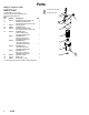
The numbers and letters in parentheses refer to Figs.
1, 2, and 3 and the Parts Drawing. Accessories and
Technical Data are on the front page.
NOTE: Allow 3 in. (76 mm) minimum clearance below
the filter for easy removal of the bowl (9).
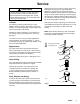
Fluid Drain Valve (required in all systems)
WARNING
A fluid drain valve is required in the base of each
fluid filter. Use this drain valve to relieve fluid pres-
sure in the filter, to reduce the risk of serious injury,
including fluid injection and splashing in the eyes or
on the skin.
Remove the 1/4 npt plug from the bottom of the filter
and install an adapter and drain valve (A,B). See
Fig. 1.
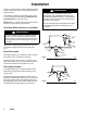
Dual Filter System
This setup enables you to redirect the fluid to another
filter while one filter is cleaned or serviced.
Install two filters as shown in Fig. 1. Install four suit-
able shutoff valves (D), one at each filter and outlet, to
redirect the fluid and isolate the filter not in use.
Filter Bypass System
This setup enables you to redirect the fluid through
pipes which bypass the filter while cleaning or serv-
icing the filter.
Install the filter and bypass pipes as shown in Fig. 2.
Install four suitable shutoff valves (D), one each at the
filter inlet, the filter outlet, the bypass pipe inlet, and
the bypass pipe outlet. These valves redirect the fluid
and isolate the filter while cleaning and servicing.
WARNING
To reduce the risk of component rupture and
serious bodily injury, do not exceed 300 psi (21
bar) Maximum Working Pressure, or the maximum
working pressure of the lowest rated component or
accessory in your system.
Be sure all components and accessories are rated
to withstand the maximum working pressure of
your pump.
Fig. 1
03709
A,
B
D
9
D
D
D
A,B
9
Fig. 2
03710
DD9
A,B