Instructions – Parts List Huskyt 205 Air–Operated Diaphragm Pumps 308652Y ENG 100 psi (0.7 MPa, 7 bar) Maximum Incoming Air Pressure 100 psi (0.7 MPa, 7 bar) Maximum Fluid Working Pressure Important Safety Instructions. Read all warnings and instructions in this manual. Save these instructions. Part No. D120XX Polypropylene Pump with Air–Operated Motor Part No. D110XX and DM10XX Acetal Pump with Air–Operated Motor Part No. D150XX and DM50XX PVDF Pump with Air–Operated Motor Part No.
Contents Warnings . . . . . . . . . . . . . . . . . . . . . . . . . . . . . . . . . . . . . 2 Installation . . . . . . . . . . . . . . . . . . . . . . . . . . . . . . . . . . . . 4 Operation . . . . . . . . . . . . . . . . . . . . . . . . . . . . . . . . . . . . . 8 Maintenance . . . . . . . . . . . . . . . . . . . . . . . . . . . . . . . . . . . 9 Troubleshooting . . . . . . . . . . . . . . . . . . . . . . . . . . . . . . . 10 Service . . . . . . . . . . . . . . . . . . . . . . . . . . . . . . . . . . . .
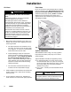
WARNING HAZARDOUS FLUIDS Improper handling of hazardous fluids or inhaling toxic vapors can cause extremely serious injury or death from splashing in the eyes, ingestion, or bodily contamination. Observe all the following precautions when you handle hazardous or potentially hazardous fluids. D Know what fluid you are pumping and its specific hazards. Take precautions to avoid a toxic fluid spill.
Installation Tightening Threaded Fasteners Before First Use Before using the pump for the first time, check and retorque all external fasteners. See Torque Sequence, page 18. After the first day of operation, retorque the fasteners. Although pump use varies, a general guideline is to retorque fasteners every two months. Use a compatible thread sealant on all male threads. Tighten all connections firmly to avoid air or fluid leaks. CAUTION To avoid pump damage, do not overtighten the fittings to the pump.
Installation Air Exhaust Ventilation . WARNING TOXIC FLUID HAZARD Read the USING HAZARDOUS FLUIDS and FIRE AND EXPLOSION HAZARD sections on page 3 before you operate this pump. Be sure the system is properly ventilated for your type of installation. You must vent the exhaust to a safe place, away from people, animals or food handling areas when pumping flammable or hazardous fluids. If the diaphragm ruptures, the fluid being pumped is exhausted with the air.
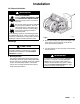
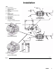
Installation Air Lines Fluid Lines WARNING Bleed-Type Master Air Valve and Fluid Drain Valve A bleed-type master air valve and a fluid drain valve are required on your system. Fig. 3. On each end of the fluid manifold are a fluid IN port and a fluid OUT port. NOTE: Make sure the fluid OUT port on the fluid manifold is mounted up. This will assure proper pump priming. Fluid-in and fluidout lines can be connected on the same end, or opposite ends of the manifold.
Installation KEY A B C Husky 205 pump Bleed-type master air valve (required for pump) Air line(s) Master air valve (for accessories) Air line filter Muffler Pump air regulator Fluid drain valve (required on fluid outlet side of pump) Fluid suction line Fluid supply hose Bung adapter 4-way solenoid Ground wire (required) See page 4 for installation instructions.
Operation Pressure Relief Procedure 3. Place the suction tube (if used) in the fluid to be pumped. WARNING To reduce the risk of serious injury, including splashing fluid in the eyes or on the skin, follow this procedure whenever you are instructed to relieve pressure, when you shut off the pump, and before you check, adjust, clean, move, or repair any system equipment. 4. Place the end of the outlet hose into an appropriate container. 5. Close the fluid drain valve. 6.
Maintenance Lubrication Flushing and Storage The air valve is lubricated at the factory and designed to operate without additional lubrication. If added lubrication is desired, every 500 hours of operation (or monthly), remove the hose from the pump air inlet and add two drops of machine oil to the air inlet. CAUTION Do not over-lubricate the pump. Excess oil is exhausted through the muffler, which could contaminate your fluid supply or other equipment.
Troubleshooting Relieve the pressure before you check or service the equipment. Check all possible problems and causes before you disassemble the pump. WARNING To reduce the risk of serious injury whenever you are instructed to relieve pressure, always follow the Pressure Relief Procedure on page 8. Internal Air Valve-Operated and Remote Solenoid-Operated Pumps PROBLEM CAUSE SOLUTION The pump cycles at stall, or it fails to hold pressure at stall. The check valves (20) or o-rings (21) are leaking.
Troubleshooting Internal Air Valve-Operated Pumps Only PROBLEM CAUSE SOLUTION The pump will not cycle, or it cycles once and stops. The air valve is stuck or dirty. Disassemble and clean or repair the air valve. See page 12. Use filtered air. Not enough air pressure supplied. Increase air pressure supply. Do not exceed maximum input pressure. Remote Solenoid-Operated Pumps Only PROBLEM CAUSE SOLUTION The pump will not prime or loses prime. The cycle rate is too low.
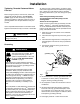
Service 2. Remove the four screws (14) that hold the valve cover (7) on the center housing (1). Service Kits Service Kits may be ordered separately. To repair the air valve, order Part No. 238853. Parts included in the Air Valve Service Kit are marked with an asterisk in the Parts Drawing on page 17, for example (3*). For fluid section repair section parts, see the Service Kit Matrix on page 15.
Service Replacing Diaphragms Replace the diaphragms as follows. See Fig. 6 and Fig 7. 1. Relieve the pressure, and disconnect the air line from the pump. 5. Remove the diaphragm pins (8), remove and replace the o-rings (9), and reinstall the diaphragm pins in the center housing (1). WARNING 6. Reinstall the diaphragm shaft (10). 7. Install the new diaphragms (30) with the concave side toward the center housing (1).
Service Replacing Check Valves Replace each pair of check valves as follows. See Fig. 7. 1. Relieve the pressure, and disconnect the air line from the pump. 3. Remove and replace the check valves (20), being careful to orient each check valve exactly like the one it is replacing. Make sure the check valve/seat area is clean. 4. Remove and replace the sealing o-rings (21). Once compressed, o-rings may not be reused. Make sure the check valve/seat area is clean.
Parts Matrix Husky 205 Polypropylene, Acetal*, and PVDF Pumps The Model Number of your pump is marked on the pump’s serial plate. To determine the Model Number of your pump from the following matrix, select the six digits that describe your pump, working from left to right. The first digit is always D, designating Husky diaphragm pumps. The remaining five digits define the materials of construction.
Parts Air Motor Section (matrix column 2) Ref. Digit No. Part No. Description Qty.
Parts Check Valve (matrix column 5) Diaphragm (matrix column 6) Digit Ref. Part No. Description Qty. Digit Ref. Part No. Description Qty.
Torque Sequence For proper installation, always follow torque sequence whenever you are instructed to torque screws. 1. Valve Cover 2. Left/Right Fluid Cover Torque bolts to 40–45 in–lb (4.5–5.0 NSm) 3 1 2 Torque bolts to 42–47 in–lb (4.7–5.3 NSm) 8 10 6 5 9 7 4 3. Manifold to Center Section Torque bolts to 42–47 in–lb (4.7–5.
Technical Data Maximum fluid working pressure . . . . . . . . . . . . . 100 psi (0.7 MPa, 7 bar) Maximum/minimum air pressure . . . . . . 100 psi/20psi (0.7 MPa, 7 bar)/(0.14 MPa, 1.4 bar) Maximum fluid flow . . . . . . . . . . . . . 5.0 gpm (18.9 lpm) Maximum pump speed . . . . 320(dry) cycles per minute 250(wet) cycles per minute Volume per stroke* . . . . . . . . . . . . . . . 0.006 gal (23 cc) Volume per cycle* . . . . . . . . . . . . . . . . 0.012 gal (46 cc) Maximum suction lift dry . . . . . . . . .
Dimensions and Mounting Hole Layout 6.0 in. 152.4 mm 3.7 in. 94 mm 5.4 in. 137 mm Four 0.175 in. x .85 in. deep 4.445 mm x 21.59 mm deep diameter holes ti10913a 3.0 in. 76.2 mm Four 0.281 in. 7.137 mm diameter holes 2.5 in. 63.5 mm Four 0.230 in. (5.8 mm) diameter holes 6.8 in.
Performance Charts Husky 205 Fluid Outlet Pressure Test Conditions: Pump tested in water with inlet submerged. FLUID OUTLET PRESSURE––psi (MPa, bar) 100 (0.7, 7) 90 (0.62, 6.2) Fluid Pressure Curves 80 (0.55, 5.5) A at 100 psi (0.7 MPa, 7 bar) air pressure B at 70 psi (0.48 MPa, 4.8 bar) air pressure C at 40 psi (0.28 MPa, 2.8 bar) air pressure 70 (0.48, 4.8) 60 (0.41, 4.1) 50 (0.35, 3.5) A 40 (0.28, 2.8) B 30 (0.21, 2.1) C 20 (0.14, 1.4) 10 (0.07, 0.7) 0 0 0.5 (1.9) 1 (3.8) 1.5 (5.7) 2 (7.
Performance Charts Husky 205 Air Consumption Test Conditions: Pump tested in water with inlet submerged. 6 (0.17) AIR CONSUMPTION––scfm (cubic meters/min) A 5 (0.14) Air Consumption Curves A at 100 psi (0.7 MPa, 7 bar) air pressure B at 70 psi (0.48 MPa, 4.8 bar) air pressure C at 40 psi (0.28 MPa, 2.8 bar) air pressure 4 (0.11) B 3 (0.09) 2 (0.06) C 1 (0.03) 0 0 0.5 (1.9) 1 (3.8) 1.5 (5.7) 2 (7.6) 2.5 (9.
Notes 308652 23
Graco Warranties Graco Standard Husky Pump Warranty Graco warrants all equipment manufactured by Graco and bearing its name to be free from defects in material and workmanship on the date of sale to the original purchaser for use. With the exception of any special, extended, or limited warranty published by Graco, Graco will, for a period of five years from the date of sale, repair or replace any part of the equipment determined by Graco to be defective.