
Installation Sheet

IOG 2241.00
Rev. 2 August 2008
1
Dear Customer Estimado Cliente
Thank you for selecting our product. We are confident we can fully satisfy Muchas gracias por elegir nuestro producto. Estamos seguros que podemos
satisfacer completamente sus expectativas ofreciéndole una amplia variedad
your expectations by offering you a wide range of technologically advanced
products which directly result from our many years of experience in faucet
de productos tecnológicamente avanzados que resultan directamente de
and fitting production.
muchos años de experiencia en grifos y su producción apropiada.
ENGLISH
~
ESPANOL
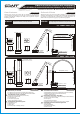
TARGA 3651-C14
Model
Modelo
SADE 1851-C14B
Model
Modelo
8-5/64" (205mm)
7-13/64" (183mm)
8-1/8" (206.5mm)
8-29/32" (226mm)
1-27/32" (47mm)
1.-57/64" (48mm)
2-33/64"
(64mm)
3" (76mm)
2-33/64"
(64mm)
2-13/16" (71.5mm)
8-47/64" (222mm)
3-7/64" (79mm)
6 " l
63/
4
(
l
25m
m)
For easy installation of your Para la instalación fácil de su grifo
GRAFF faucet you will need: de la GRAFF usted necesitará:
to READ ALL the instructions completely before beginning, LEER TODAS las instrucciones completamente antes de comenzar,
to READ ALL the warnings, care and maintenance information. LEER TODA la información sobre las advertencias,
To complete the project, you should: cuidado y mantenimiento.
gather the tools and all the parts you will need, Para terminar el proyecto, usted debe:
prepare the mounting area, recolectar las herramientas y todas las piezas que usted necesitará,
mount the faucet, prepare el área para el montaje,
connect the supply lines, monte el grifo,
finally test and flush the faucet. conecte las líneas de fuente,
You should have the following tools: finalmente pruebe y limpie el grifo con un chorro de agua.
Usted debe tener las herramientas siguientes:
adjustable wrench,
llave ajustable,
channel pliers,
®
alicates acanalados,
Teflon tape,
®
cinta adhesiva de Teflon ,
plumbers putty or caulking (silicone).
masilla o silicona.
l l
l l
l
l l
l l
l l
l l
l
l
l
l
l
l
l
l
l
ENGLISH
~
ESPANOL
11-17/32" (293mm)
6-3/8" (162mm)
8-55/64" (225mm)
1-1/64"
(26mm)
6-3/8" (162mm)
2-33/64"
(64mm)
8-47/64" (222mm)
1-27/32" (47mm)
1.-57/64" (48mm)
2-33/64"
(64mm)
3" (76mm)
2-13/16" (71.5mm)
3-7/64" (79mm)
6 "
l63
/
4
(l
25mm)
For care, use soft towel with soap and water only! Under no
circumstances should you use any chemicals.
ATTENTION!
ATENCIÓN!
Para el cuidado, utilice solamente una toalla suave con jabón
y aqua! Bajo ninguna circunstancia no use productos químicos.
This faucet complies with ASME/ANSI A112.18.1
and CSA B 125 Standards.
Este grifo se encuentra conforme con losestandares
de ASME/ANSI A112.18.1 y de CSA B 125.
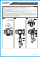
Installation Instructions l Instrucciones de Instalación
ROMAN TUB SET WITH BUILT-IN DIVERTER VALVE & HANDSHOWER
GRIFO DE BAÑERA CON VÁLVULA DE DESVIADOR INCORPORADA Y CON LA TELEDUCHA
SET-UP DIAGRAM l DIAGRAMA DE INSTALACIÓN
1
IOG 2241.00
Rev. 2 August 2008
2
max. 1-1/2"
(max. 38mm)
3/4-14NPT
3/4-14NPT
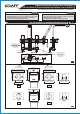
Cold water valve is marked
with blue sticker
La válvula de agua fria
está marcada con
le etiqueta azul
Hot water valve is marked
with red sticker
La válvula de agua caliente
está marcada con
le etiqueta roja
Ø1.65" (Ø42mm)
0.73"
(18.5mm)
0.83"
(21mm)
4" (101.6mm) 4" (101.6mm) 4" (101.6mm)
Ø1.61"
(Ø41mm)
Ø1.61"
(Ø41mm)
Ø0.24"
(Ø6mm)
0.71"
(18mm)
1.69"
(43mm)
MIN.Ø1.06" - MAX.Ø1.34"
(MIN.Ø27mm - MAX.Ø34mm)
ANTES DE LA INSTALACIÓN
Antes de instalar el grifo, es bueno ejuagar las tuberías
suministro para eliminar residuos.
Recomendamos el instalar los tapones de filtro.
l
l
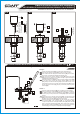
BEFORE INSTALLING
Before installing the faucet, it is good to rinse the supply
pipelines in order to do away with the dirty residues.
We recommend installing the filter taps.
l
l
ENGLISH
~
ESPANOL
1A
1B
ON ON
1-57/64" (48mm)
2-33/64" (64mm)
2-13/16" (71.5mm)
3" (76mm)
2-33/64" (64mm)
1-57/64" (48mm)
1-57/64" (48mm)
1-57/64" (48mm)
2-33/64" (64mm)
1/4 TURN
1/4 DE VUELTA
1/4 TURN
1/4 DE VUELTA
COUNTERCLOCKWISE OPENING
SE ABRE HACIA LA IZQUIERDA
OFF OFF
CLOCKWISE OPENING
SE ABRE HACIA LA DERECHA
This faucet complies with ASME/ANSI A112.18.1
and CSA B 125 Standards.
Este grifo se encuentra conforme con losestandares
de ASME/ANSI A112.18.1 y de CSA B 125.
Installation Instructions l Instrucciones de Instalación
ROMAN TUB SET WITH BUILT-IN DIVERTER VALVE & HANDSHOWER
GRIFO DE BAÑERA CON VÁLVULA DE DESVIADOR INCORPORADA Y CON LA TELEDUCHA
ENGLISH
~
ESPANOL
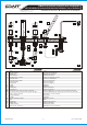
SPOUT
AERATOR INSERT
RUBBER PAD
STEEL WASHER
MOUNTING NUT (2 pieces)
DIVERTER VALVE
DIVERTER SWITCH KNOB
HANDLE ASEMBLY
HANDLE BASE
SCREW
WASHER
FLANGED NUT
COUNTER NUT
RIGHT VALVE (with clockwise opening cartridge)
LEFT VALVE (with counterclockwise opening cartridge)
HOSE 11-13/16” (300mm)
SHOWER HANDSET
WASHER
SHOWER HANDSET SOCKET
BASE
RUBBER PAD
FLANGED NUT
RUBBER WASHER
HOSE 59-1/16” (1500mm)
GRIFO
INSERTOR DEL AEREADOR
ARANDELA DE CAUCHO
ARANDELA DE METAL
TUERCA DE MONTAJE (2 piezás)
VÁLVULA DE DESVIADOR
BOLA DEL DESVIADOR
JUEGO DE MANILLA
BASE DE LA MANILLA
TORNILLO
ARANDELA
TUERCA CON BRIDA
TUERCA DE CONTRA
VÁLVULA DERECHA (con cartucho que se abre hacia la derecha)
VÁLVULA IZQUIERDA (con cartucho que se abre hacia la izquierda)
MANGUERA 11-13/16” (300mm)
TELEDUCHA
ARANDELA
ASIENTO DE DUCHA
BASE
ARANDELA DE CAUCHO
TUERCA CON BRIDA
ARANDELA DE GOMA
MANGUERA 59-1/16” (1500mm)
1
2
3
4
5
6
7
8
9
10
11
12
13
14A
14B
15
16
17
18
19
20
21
22
23
10 10
8 1
9
11
3
12
4
13
15
5
14B 14A
16
17
23
7
2
6
22
23
15
6
18
19
20
21
IOG 2241.00
Rev. 2 August 2008
3
3/4-14NPT 3/4-14NPT
2
This faucet complies with ASME/ANSI A112.18.1
and CSA B 125 Standards.
Este grifo se encuentra conforme con losestandares
de ASME/ANSI A112.18.1 y de CSA B 125.
Installation Instructions l Instrucciones de Instalación
ROMAN TUB SET WITH BUILT-IN DIVERTER VALVE & HANDSHOWER
GRIFO DE BAÑERA CON VÁLVULA DE DESVIADOR INCORPORADA Y CON LA TELEDUCHA
IOG 2241.00
Rev. 2 August 2008
4
ENGLISH
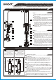
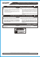
See fig. 3
Insert spout (1) with shanks (A) through the central
hole in the deck. Center spout over side hole of
mounting surface.
From underneath the ledge place rubber washer (3),
metal washer (4) on the shanks (A), then screw on
the mounting nuts (5). Hand tighten only.
From underneath the ledge align diverter valve (6)
with the spout axis as shown on fig. 1A. Put diverter
switch (B) through the spout base hole, then screw on
the coupling nuts (C) onto shanks (A). Make sure that
the washers are in the coupling nuts (C). Screw on the
knob (7) onto diverter switch (B) and check the
correct operation of diverter switch.
Make sure that the spout is in proper position on the
bath tub ledge. Tighten the mounting nuts (5) using
adjustable wrench.
Vea dis. 3
Inserte el grifo (1) con tubos de conexión (A) a través
del agujero central en la cubierta. Centre el grifo en el
agujero lateral de la superficie de montaje.
Por debajo del borde coloque la arandela de goma (3)
y la arandela de metal (4) en los tubos de conexión
(A), luego enrosque las tuercas de montaje (5).
Apriete únicamente a mano.
Por debajo del borde coloque la válvula del desviador
(6) con el eje situado como lo muestra la dis. 1A.
Poner el conectador del desviador (B) a traves del
agujero en la base del grifo, luego enroscar las tuercas
(C) sobre los tubos (A). Verifique si las arandelas
están sobre las tuercas (C). Enroscar la bola (7) en el
conectador del desviador (B) y verificar si el desviador
funciona correctamente.
Asegúrese de que el grifo se encuentra en la posición
apropiada en el borde de la bańera. Ajuste las tuercas
de montaje (5) usando la llave inglesa.
~
ESPANOL
SPOUT AND DIVERTER VALVE INSTALLATION l INSTALACIÓN DEL GRIFO Y DE LA VÁLVULA DE DESVIADOR
2
1
A
3
4
5
C
6
7
B
1
A
3
4
B
5
C
6
HANDLES INSTALLATION l INSTALACIÓN DE LAS MANILLAS
3
Place handle base (9) and center over side hole of mounting surface – see
fig. 1B and 5.1.
From underneath the ledge place the washer (11) and then screw the
flanged nut (12) (fig. 5.1).
Turn the spline of a cartridge in a valve (14A) & (14B) to OFF position:
l in the hot water valve (fig. 4.1): left valve marked with the red sticker
turn the cartridge spline (A) in clockwise direction,
l in the cold water valve (fig. 4.2): right valve marked with the blue
sticker turn the cartridge spline (B) in counterclockwise direction.
Thread the counter nut (13) onto the valve (14A) [and (14B)] as show
fig. 5.2.
From underneath the ledge thread the valve (14A) [and (14B)] to the
handle base (9) until the spline of the cartridge (A) [and (B)] protrudes
from the hole see fig. 5.3. Tighten lightly the counter nut (13) on the valve
(14A) [and (14B)].
Put the hex key into the hole of the slide ring (R) and rotate the ring (R) so
that the hole in the ring is in bottom position facing the hex set screw (10)
in the base plate (9). Remove the hex key from the hole and push in the
handle assembly (8) onto cartridge spindle - see fig. 5.4- 5.5. Set the
handle (8) as on fig. 1B “OFF” position.
Block carefully the handle (8) with a set screw (10) using the hex key
(included with the faucet). A screw pin should enter the hole in the slide ring
(R). In case of excessive pressure and difficulties with rotation of the handle
loosen up the set screw (10) by a ¼ turn (fig. 5.6).
Tighten the counter nut (13) on the valve (14A) [and (14B)].
ENGLISH
4.1
4.2
Turn spline of cartridge (A)
to OFF position
max. cklockwise direction
Luego girar la polichaveta de
cartucho (A) en la posicón OFF
maximo hacia la derecha
Turn spline of cartridge (B)
to OFF position
max. countercklockwise direction
Luego girar la polichaveta (B) de
cartucho en la posicón OFF
maximo hacia la izquierda
A
14B
Hot water valve is marked with red sticker
La válvula de agua caliente esta
marcada con le etiqueta roja
B
14A
Cold water valve is marked with blue sticker
La válvula de agua fría esta
marcada con le etiqueta azul
See fig. 4.1-4.2, 5.1-5.6
3
This faucet complies with ASME/ANSI A112.18.1
and CSA B 125 Standards.
Este grifo se encuentra conforme con losestandares
de ASME/ANSI A112.18.1 y de CSA B 125.
Installation Instructions l Instrucciones de Instalación
ROMAN TUB SET WITH BUILT-IN DIVERTER VALVE & HANDSHOWER
GRIFO DE BAÑERA CON VÁLVULA DE DESVIADOR INCORPORADA Y CON LA TELEDUCHA