FH16-D Flow heaters Operating instructions
Type: FH16 - D
Flow Heaters CONTENTS 1 Safety 4 2 2.1 2.2 2.2.1 2.2.2 2.2.3 2.2.4 2.2.5 2.2.6 Installation Unpacking Assembly Open tanks Closed systems Low volume Low flow rates Working below room temperature Temperature sensors 5 5 5 5 5 5 5 5 5 3 3.1 3.1.1 3.1.2 3.1.3 3.1.4 3.1.5 3.1.6 3.1.7 3.2 3.3 3.3.1 3.3.2 3.3.
Flow Heaters 1 Safety The following symbols marked on the equipment mean:Caution: Read these operating instructions fully before use and pay particular attention to sections containing this symbol Caution: Surfaces can become hot during use. Always observe the following safety precautions • • • • • • • • • • • • • • • • • • • • • • • Use only as specified by the operating instructions, or the intrinsic protection may be impaired.
Flow Heaters 2 2.1 Installation Unpacking Remove packing materials carefully, and retain for future shipment or storage of the unit. Packs should contain: Flow heater Operating instruction 2.2 Assembly 2.2.1 Open tanks Connect the outlet pipe of FH to the input pipe at the bottom of the tank. Return to the FH from the top of the tank. Fill the tank, then fill the flow heater and tubing from a low pressure water supply or with a hand syphon pump.
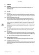
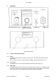
Flow Heaters 3 Operation Set overtemperature cutout Inlet pipe Temperature control Figure 1 (front view) Mains lead Probe socket Mains switch Outlet pipe Figure 2 (rear view) 3.1 Controls and indicator lamps 3.1.1 Power The power (mains) switch is located on the front panel. The switch is illuminated when the power is ON. If the unit does not come on, check whether the "alarm" lamp is illuminated (see 3.1.6). 3.1.
Flow Heaters 3.1.4 Temperature display Digital units The temperature display normally shows the temperature in °C of liquid being controlled. It displays set temperature when the push to set °C knob is pressed. Analogue units The set temperature is indicated on the dial. 3.1.5 Set temperature knob Digital units Push to set °C Press knob to change display from liquid temperature to set temperature, and at the same time rotate the knob to set the required operating temperature.
Flow Heaters 3.3 Switching on and setting up 3.3.1 Connection to supply Connect the inlet and outlet pipes to your external circuit. Connect the control unit to a grounded (earthed) electrical power supply with voltage and frequency within the range specified on the serial number plate. DO NOT SWITCH ON BEFORE FILLING THE SYSTEM. Running with no liquid in the pump can destroy the pump Before switching on for the first time, turn the set overtemperature control fully clockwise.
Flow Heaters 4.2 BS15 filler/de-aerator and bypass system Good temperature control depends on an adequate flow through the flow heater. If narrow tubes or small cells restrict flow, a bypass system is required. The bypass ensures that most of the flow takes place in a large bore loop, with a smaller flow through the external circuit.
Flow Heaters 6 Technical Specification This equipment is for indoor use and will meet its performance figures within an ambient temperature range 10 to 35°C with maximum relative humidity of 80%. Installation category II (transient voltages). Pollution degree 2 in accordance with IEC 664. For operation at altitudes up to 2000 metres. Temperature Range Stability (DIN 58966) at 37°C Supply voltage range FH16 - D Ambient 15°C to 80°C (FC1 is required for operation at or below ambient) ± 0.
Flow Heaters 7.2 Replacement of fuses Digital unit Disconnect the unit from the power supply socket. Locate the fuses on the front panel. Use screwdriver of correct size to turn the fuse holder cap a quarter turn anti-clockwise to release the fuse holder cap. Check and replace fuse if necessary. Replace with the correct fuse: 1.25 x 0.25 inch ceramic quick acting.
Flow Heaters Grant Instruments (Cambridge) Ltd Shepreth Cambridgeshire SG8 6GB England Tel: +44 (0) 1763 260811 Fax: +44 (0) 1763 262410 Email: kevin.hardy@grant.co.uk www.grant.co.
Flow Heaters Part No: 15630/Issue 3 Page 13 March 2003