
Manual


Flow Heaters
Part No: 15630/Issue 3 Page March 2003
5
2 Installation
2.1 Unpacking
Remove packing materials carefully, and retain for future shipment or storage of the unit.
Packs should contain:
Flow heater
Operating instruction
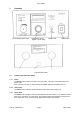
2.2 Assembly
2.2.1 Open tanks
Connect the outlet pipe of FH to the input pipe at the bottom of the tank. Return to the FH from
the top of the tank. Fill the tank, then fill the flow heater and tubing from a low pressure water
supply or with a hand syphon pump. Disconnect the supply tubing under water to avoid letting air
into the system.
2.2.2 Closed systems (BS15 cannot be used)
Fit a T-connection and a tap at the highest and lowest accessible points of the system. Fill
through the lower tap from a low pressure water supply or with a hand syphon pump; clear air
through the upper tap. Close the taps and switch on. Trapped air in the liquid can cause
damage to the pump and reduce the flow rate. Ensure that all hose clips are tight or air may be
drawn in at the joints. To clear air from the liquid, switch the circulator on and off at 15 second
intervals. Repeat until no bubbles of air are seen to come out of liquid in the pipes and pump
runs quietly.
To prevent excessive pressures occurring when circulating liquid in any closed loop system,
allowances for the expansion of the liquid with temperature must be made. Therefore the system
should not be filled to more than 95% of its total volume, thus leaving 5% for expansion at the
top of the system.
2.2.3 Low volume
If the volume of liquid within the system is low, less than one litre, temperature control can be
improved by adding an insulated reservoir between the flow heater output and the external
apparatus.
2.2.4 Low flow rates
Use a BS15 bypass if the external apparatus has restrictions which reduce the flow rate below
two litres per minute; connect the upper large pipe (15mm outside diameter) on the BS15 to the
flow heater outlet and the lower to the inlet. Connect the small pipes (6 mm outside diameter)) to
the external apparatus. Fill by removing the top cap and filling through the small header/vent
tank. Remove air as above, keeping BS15 the full by adding liquid as necessary.
2.2.5 Working below room temperature
When a BS15 bypass is used, connect the flow cooler between the BS15 and the FH inlet.
FC1 water cooled flow cooler can be used for temperatures down to 15°C above tap water.
2.2.6 FH16 - D external temperature sensor
Use for improved control in external apparatus. Control is assumed by the external sensor when
it is plugged in to the socket. The tip of the external sensor should always be immersed at least
25mm in the circulating liquid. Position the sensor at the point in the system at which optimum
control is required.