
Manual


Flow Heaters
Part No: 15630/Issue 3 Page March 2003
6
3 Operation
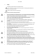
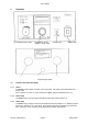
Figure 1 (front view)
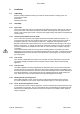
Inlet pipe Mains lead Outlet pipe
Figure 2 (rear view)
3.1 Controls and indicator lamps
3.1.1 Power
The power (mains) switch is located on the front panel. The switch is illuminated when the
power is ON.
If the unit does not come on, check whether the "alarm" lamp is illuminated (see 3.1.6).
3.1.2 Power lamp
The power lamp on the front panel indicates that the mains power supply is on.
3.1.3 Heater lamp
The heater lamp (orange) on the front panel indicates when the heater is on. While the liquid is
warming up, the lamp is on continuously, and it starts to flash as the temperature reaches set
point. When the unit is controlling at set temperature it flashes intermittently.
Temperature control
Probe socket Mains switch
Set overtemperature cutout