
Manual


Flow Heaters
Part No: 15630/Issue 3 Page March 2003
8
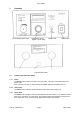
3.3 Switching on and setting up
3.3.1 Connection to supply
Connect the inlet and outlet pipes to your external circuit.
Connect the control unit to a grounded (earthed) electrical power supply with voltage and
frequency within the range specified on the serial number plate.
DO NOT SWITCH ON BEFORE FILLING THE SYSTEM.
Running with no liquid in the pump can destroy the pump
Before switching on for the first time, turn the set overtemperature control fully clockwise. Press
the knob to ensure that it is reset.
Switch the power on and check that the power lamp is illuminated.
3.3.2 Setting temperature
Press the push to set °C knob and rotate to set the required operating temperature.
Wait until the liquid temperature has stabilised at the operating temperature.
3.3.3 Over-temperature cut-out
After the temperature has stabilised at the required set temperature, adjust the set
overtemperature control as follows:
Turn the control anticlockwise, using a screwdriver, until the alarm lamp comes on. Press the
knob to reset it and turn slowly clockwise until the alarm lamp goes out. This gives an
overtemperature trip point of approximately 30°C above set temperature.
If a trip temperature nearer to the set temperature is required, note the position of the set
overtemperature control at the points where the alarm lamp comes on and where it goes off.
Then turn the control anticlockwise three quarters of the way back towards the point where the
alarm lamp came on. This prevents liquid temperature rising more than about 10°C above set
temperature in the event of a malfunction.
4 Accessories
4.1 FC1
FC1 water-cooled heat exchanger is designed for use with tap water, and can be used when the
required operating temperature is 2°C or more above the temperature of the tap water, down to a
minimum of 15°C. Inlet and outlet pipes are 15mm o.d, cooling water connection 6mm o.d. If a
lot of heat is produced in the external equipment, and FC1 flow cooler can be placed.