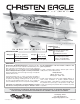
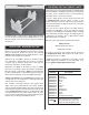
.46 – .72/EP ARF The Christen Eagle name is used by Hobbico®, Inc. under license from Aviat Aircraft, Inc. Length: INSTRUCTION MANUAL Radio: SPECIFICATIONS Wingspan: Top: 42.5 in [1080mm] Bottom: 40 in [1015mm] Wing Area: 441 in2 [28.4 dm2] Weight: 5.75– 6.25 lb [2610– 2830 g] Wing Loading: 30– 33 oz/ft2 [92 – 101 g /dm2] Engine: 39.5 in [1005mm] 4-Channel minimum with 4 – 7 servos and standard size receiver .46 – .55 cu in [7.5 – 9cc] two-stroke .72 cu in [12cc] four-stroke RimFire™ .
TABLE OF CONTENTS INTRODUCTION INTRODUCTION . . . . . . . . . . . . . . . . . . . . . . . . . . . . . . . .2 AMA . . . . . . . . . . . . . . . . . . . . . . . . . . . . . . . . . . . . . . . . . .2 SAFETY PRECAUTIONS . . . . . . . . . . . . . . . . . . . . . . . . .2 DECISIONS YOU MUST MAKE. . . . . . . . . . . . . . . . . . . . .3 Radio Equipment . . . . . . . . . . . . . . . . . . . . . . . . . . . . .3 Power System Recommendations . . . . . . . . . . . . . . . .3 Propeller. . . . . . . . . . . . . . .
2. You must assemble the model according to the instructions. DECISIONS YOU MUST MAKE Do not alter or modify the model, as doing so may result in an unsafe or unflyable model. In a few cases the instructions may differ slightly from the photos. In those instances the written This is a partial list of items required to finish the Christen Eagle .46 ARF that may require planning or decision making instructions should be considered as correct. before starting to build. Order numbers are provided in 3.
❏ Great Planes Tap & Drill Set 6-32 (GPMR8102) (Glow Propeller engine installation only) ❏ Tap handle (GPMR8120) (Glow engine installation only) ❏ Dead Center™ Engine Mount Hole Locator (GPMR8130) ❏ Rotary tool with cutting bit ❏ Revell® Premium Soft Handle Knife w/Blades (5) If you are installing a glow engine, choose a prop based on the engine manufacturer’s recommendation. If you are installing the recommended RimFire brushless motor, we suggest a 13x10E APC propeller.
Building Stand ORDERING REPLACEMENT PARTS Replacement parts for the Christen Eagle are available using the order numbers in the Replacement Parts List that follows. The fastest, most economical service can be provided by your hobby dealer or mail-order company. To locate a hobby dealer, visit the Great Planes web site at greatplanes.com. Choose “Where to Buy” at the bottom of the menu on the left side of the page. Follow the instructions provided on the page to locate a U.S.
KIT INSPECTION Before starting to build, take an inventory of this kit to make sure it is complete, and inspect the parts to make sure they are of acceptable quality. If any parts are missing or are not of acceptable quality, or if you need assistance with assembly, contact Product Support. When reporting defective or missing parts, use the part names exactly as they are written in the Kit Contents list.
PREPARATIONS ❏ 1. If you have not done so already, remove the major parts of the kit from the box and inspect for damage. If any parts are damaged or missing, contact Product Support at the address or telephone number listed in the “Kit Inspection” section on the opposite page. CUT OFF UNUSED ARMS ❏ ❏ 2. Cut three arms from a four-armed servo arm for each aileron servo. Enlarge the outer hole of each remaining arm with a 5/64" [2mm] drill bit. ❏ 2.
into the blocks. Thread a servo mounting screw (included with the servos) into each hole and back it out. Apply a drop of thin CA to each hole to harden the wood. When the CA has dried, install the servos onto the hatch covers using the hardware supplied with the servos. ❏ ❏ 5. Epoxy the aileron mounting blocks onto the hatch covers. Allow the epoxy to harden completely before moving on. ❏ ❏ 6. Drill a 1/16" [1.6mm] hole through the hatch cover and through each aileron mounting block.
glue to each hole to harden the wood. When the glue has dried, install the control horns onto the ailerons using four 2-56 x 1/2" [13mm] machine screws and the control horn backplates. ❏ ❏ 10. Thread a nylon clevis 20 complete turns onto two 4" [102mm] pushrods. Slide a silicone clevis retainer onto each clevis and connect the clevises to the outer holes of two small control horns. CORRECT INCORRECT Servo Horn Hinge Line 2-56 (.074") Pushrod Wire Hinge Line Hi ❏ ❏ 11.
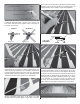
HOW TO CUT COVERING FROM BALSA Use a soldering iron to cut the covering from the area beneath the belly pan. The tip of the soldering iron doesn’t have to be sharp, but a fine tip does work best. Allow the iron to heat fully. ❏ 15. Glue the bottom wing dowels into the holes in the leading edge. Position the dowels so that 3/8" [9.5mm] protrudes beyond the holes. ❏ 16. Mount the bottom wing to the fuselage using two 1/4-20 x 2" [51mm] nylon wing bolts.
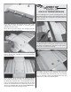
INSTALL THE TAIL SURFACES ❏ 3. Measure the distance from the corners of the ailerons on the wing to the tips of the stab. Adjust the stab until the distance from the tip of the stab to the wing is equal on both sides. Before gluing the stab, test fit the vertical fin part way into the fuse and confirm the fuse sides fit snugly against the fin. If the fit is loose, leave the fin in place while gluing the stab into the slot and use small clamps to hold the fuse sides against the fin. ❏ 1.
DRILL A 5/64" [2mm] HOLE, 3/8" [9.5mm] DEEP, IN CENTER OF HINGE SLOT ❏ 5. Confirm that the vertical fin is square with the horizontal stab. When satisfied, glue it in place (even with the back of the fuselage) in the same manner. ❏ 6. The wing can now be removed from the fuselage. CUT THE COVERING AWAY FROM THE SLOT ❏ 9. Drill a 5/64" [2mm] hole 3/8" [9.5mm] deep in the center of each hinge slot in the horizontal stabilizer and elevators.
❏ 11. Test fit the elevators to the hinges and align the outside ❏ 14. Test fit the tail wheel wire into the hole in the rudder. edges with the edges of the stab. Make any adjustments to the hinge slots if necessary. Test fit the rudder onto the fuselage with CA hinges but do not glue them yet. ❏ 12. Fit the elevator halves to the hinges in the stab. Remove ❏ 15. When satisfied with the fit, remove the rudder from the fuse and the tail wheel wire from the rudder.
INSTALL THE TAIL PUSHRODS & SERVOS ❏ 4. Trim the bottom corner from the rudder control horn. Install the control horn onto the right side of the rudder in the same manner of the elevator using two 2-56 x 1/2" [13mm] machine screws and a backplate. Be sure that the control horn is inline with the rudder pushrod exit slot. ❏ 1. Thread a nylon clevis 20 turns onto two 17-1/2" [445mm] pushrods. Slide a silicone clevis retainer onto each clevis. ❏ 5.
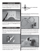
❏ 7. Make a 90° bend at the marks on the pushrods and cut ❏ 3. Slide a 5/32" [4mm] wheel collar followed by a wheel off the excess pushrod 1/4" [6mm] beyond the bends. Attach the pushrods to the servo arms using nylon FasLinks. Thread the clevises up or down on the pushrods as necessary to center the control surfaces with the servo arms centered. When satisfied, slide the silicone clevis retainers to the ends of the clevises to secure them. and then another wheel collar onto each axle.
❏ 7. Mount the main landing gear to the fuselage using four ❏ 10. Install the tail wheel onto the tail wheel wire and secure it in place with a 3/32" [2.4mm] wheel collar, 4-40 set screw and threadlocking compound. Be sure that the wheel rotates freely on the wire. 6-32 x 1/2" [13mm] SHCS, four #6 flat washers, four #6 lock washers and thread locking compound. INSTALL THE POWER SYSTEM Glow Engine Installation The Christen Eagle is designed to be flown with a .46-.55 two-stroke glow engine, .
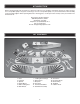
Top of Tank Vent Fill and Carb Lines ❏ 2. Insert four 6-32 blind nuts into the back of the firewall. Use a 6-32 x 3/4" [19mm] SHCS and a #6 flat washer to draw the blind nuts tight into the firewall. ❏ 4. Fit the stopper assembly into the tank with the vent line pointing toward the top of the tank, but not touching. The fuel tubing and clunks (fuel pickup) on the carb and fill lines should almost reach the back of the tank but not touch.
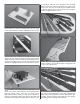
❏ 8. Install the engine mount to the firewall using four 6-32 x 3/4" [19mm] SHCS, four #6 flat washers, four #6 lock washers and thread locking compound. Leave the screws slightly loose. Test fit your engine between the mount halves. Slide the mount halves against the sides of the engine and finish tightening the mount screws. ❏ 6. Insert the tank into the fuselage so the tank neck passes through the hole in the firewall. Cut a piece from the included 3/16" x 3/8" [4.8mm x 9.
❏ 13. Cut four arms from a five-armed servo arm included ❏ 10. Attach the engine to the mount using four 6-32 x 3/4" [19mm] screws, four #6 flat washers and four #6 lock washers. with your throttle servo. Center the servo with your radio system (throttle stick positioned at 50% throttle) and install the arm perpendicular to the servo case. Install a screwlock pushrod connector into the outer hole in the remaining arm and secure it in place with a nylon screw-lock connector retainer.
❏ 18. The aft end of the pushrod should pass through the screw-lock connector. Adjust the pushrod position in the connector so that the throttle servo properly opens and closes the carburetor. When satisfied, tighten the SHCS in the connector against the pushrod and cut off the excess pushrod 1/4" [6mm] behind the connector. Use the radio system to test the operation of the throttle. ❏ 16. Insert the 12" [305mm] outer pushrod tube through the firewall and former but do not glue it yet.
Brushless Motor Installation The Christen Eagle is designed to be flown with a .46-.55 two-stroke glow engine, .72 four-stroke glow engine, or a brushless outrunner motor. If you have installed a glow engine, skip this section as it only contains information relevant to installing a brushless motor. Be sure to read and understand the instructions that come with the ESC and motor before attempting to operate the system. ❏ 1. Use an 11/64" [4.
❏ 5. Attach the motor mount to the firewall using four 6-32 x 1/2" [13mm] SHCS, four #6 flat washers, four #6 lock washers and thread locking compound. Loosen the screws that hold the two motor mount halves together. Set the distance between the firewall and the front of the prop adapter to be 4-13/16" [122mm]. Retighten the screws with thread locking compound. Take care not to inadvertently add any up or down thrust when altering the length of the motor mount. ❏ 8.
❏ 10. Attach a 6" [152mm] servo extension to the receiver battery using a piece of heat shrink tubing to secure the connection. Connect the ESC to the motor and route the receiver and battery wires through the firewall toward the servos. Now would be a good time to test the operation of the motor using your radio system. The motor should rotate counter-clockwise when looking at it from the front. If it rotates the wrong direction simply swap two of the three motor leads.
❏ 3. If you have installed a glow engine, strap the receiver pack to the tray in front of the receiver. Pieces of scrap fuel tubing have been glued to the tray to align the dual 2.4GHz receiver antennas in the orientation described in the radio manual. ❏ 2. If necessary, enlarge the hole in the spinner backplate to match your crankshaft or prop adapter. Place the cowl onto the fuselage and then the spinner backplate onto the motor.
❏ 4. Install the propeller, prop washer, prop nut, and spinner ❏ 3. Route 12" [305mm] servo leads through the holes that cone. It may be necessary to enlarge the propeller slots in the spinner cone to fit over your prop. you trimmed the covering from (if applicable) and connect the leads to your receiver with a Y-harness. Install the Wings and Struts ❏ 4. Bolt the bottom wing to the fuselage. Attach the interplane struts to the bottom wing by inserting the aluminum tabs into the slots.
❏ 6. Connect the top aileron servo lead extensions (if applicable) and then tape the connectors to the insides of the cabanes. Be sure that you can easily connect and disconnect the top wing. Steps 7-10 should only be completed if you did not install servos in the top wing. If you did install servos in the top wing, skip to step 11. ❏ 9. Thread a nylon clevis 20 turns onto each of the remaining 12" [305mm] pushrods. Fit a silicone clevis retainer onto each clevis.
Install the Canopy/Hatch ❏ 11. The base of the canopy hatch has a partial laser cut line that is cut through the majority of the perimeter of the hatch. If you wish to remove the base of the hatch to install additional cockpit details of your choice, use a sharp hobby knife to finish the cut lines. If you choose to not remove the base, apply a bead of medium or thick CA glue around the cut lines and allow it to harden. ❏ 14. This completes the assembly of the Christen Eagle .46 ARF! Apply the Decals 1.
batteries with lower voltage will try to “equalize” with the batteries that have a higher voltage. Current will flow from the higher voltage battery into the lower one, essentially “charging” the lower voltage battery pack. This situation will likely cause heat and possibly a fire. GET THE MODEL READY TO FLY Install and Operate the Motor Battery (Brushless Only) NO!!! IMPORTANT: If using multiple battery packs that are connected with an adapter, never charge the batteries together through the adapter.
Set the Control Throws Balance the Model (C.G.) More than any other factor, the C.G. (balance point) can have the greatest effect on how a model flies, and may determine whether or not your first flight will be successful. If you value this model and wish to enjoy it for many flights, DO NOT OVERLOOK THIS IMPORTANT PROCEDURE. A model that is not properly balanced will be unstable and possibly unflyable.
PREFLIGHT Identify Your Model No matter if you fly at an AMA sanctioned R/C club site or if you fly somewhere on your own, you should always have your name, address, telephone number and AMA number on or inside your model. It is required at all AMA R/C club flying sites and AMA sanctioned flying events. Fill out the identification tag on page 35 (or on the decal sheet) and place it on or inside your model. Charge the Batteries ❏ 3.
Ground Check • Make all engine adjustments from behind the rotating propeller. If the engine is new, follow the engine manufacturer’s • The engine gets hot! Do not touch it during or right after operation. Make sure fuel lines are in good condition so fuel instructions to break-in the engine. After break-in, confirm will not leak onto a hot engine, causing a fire. that the engine idles reliably, transitions smoothly and rapidly to full power and maintains full power—indefinitely.
shall be utilized to supervise flying to avoid having models fly in the proximity of full-scale aircraft. 3) Where established, I will abide by the safety rules for the flying site I use, and I will not willfully and deliberately fly my models in a careless, reckless and/or dangerous manner. 5) I will not fly my model unless it is identified with my name and address or AMA number, on or in the model. Note: This does not apply to models while being flown indoors.
Take it easy with the Eagle for the first few flights, gradually getting acquainted with it as you gain confidence. Adjust the trims to maintain straight and level flight. After flying around for a while and while still at a safe altitude with plenty of fuel, practice slow flight and execute practice landing approaches by reducing the throttle to see how the model handles at slower speeds. Add power to see how the model climbs as well.
OTHER PRODUCTS AVAILABLE FROM GREAT PLANES Great Planes® 70" Revolver™ GP/EP ARF The bigger, better Revolver! Wingspan: 70 in (1780 mm) Wing Area: 832 in² (53.7 dm²) Weight: 8.5-9.3 lb (3850-4190 g) Wing Loading: 24-26 oz/ft² (73-79 g/dm²) Length: 58.5 in (1460 mm) Requires: ires: 4-channel radio w/5 servos, 2-stroke .61-.75 or 4-stroke .81-.91 engine or RimFire™ .80 outrunner BL motor, 60A BL ESC (min) & two 11.
Futaba® 6EX 2.4GHz Computer Radio Superior full-range capability comes to 2.4GHz technology. Once you’ve experienced the 6EX 2.4GHz FASST system, you won’t want to fly any other way! The secret is the all-in-one R606FS receiver: its compact size and light weight makes it easy to mount and perfect for park flyers — but it’s also powerful enough to control any type of R/C aircraft, including electric, gasoline-powered and giant-scale planes as well as helis.