
User Manual

9
❏ ❏
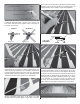
10. Thread a nylon clevis 20 complete turns onto two
4" [102mm] pushrods. Slide a silicone clevis retainer onto
each clevis and connect the clevises to the outer holes of
two small control horns.
Hinge Line Hinge Line
CORRECT INCORRECT
Hi
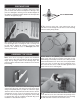
❏ ❏
11. Position the control horns over the plywood plates
in the ailerons (if you cannot see them, hold the aileron at a
shallow angle in good lighting or use a small pin to puncture the
covering) using the position of the servo arms as a guide. Align
the holes in the control horns directly over the aileron hinge line
and mark the location of the control horn mounting holes.
❏ ❏
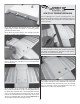
12. Drill 5/64" [2mm] holes at the marks you made
through the plywood plates. Apply a couple drops of thin CA
glue to each hole to harden the wood. When the glue has dried,
install the control horns onto the ailerons using four 2-56 x 1/2"
[13mm] machine screws and the control horn backplates.
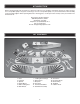
Servo Horn
1/16"
2-56 (.074")
Pushrod Wire
FasLink
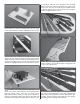
❏ ❏
13. Use tape or a small clamp to hold the ailerons in the
neutral position. Make a mark on the pushrods where they
cross the outer holes in the servo arms. Make a 90° bend at
the mark on the pushrod and cut off the excess pushrod 1/4"
[6mm] beyond the bend. Attach the pushrods to the servo
arms using nylon FasLinks. Thread the clevises up or down
on the pushrods as necessary to center the ailerons with
the servo arms centered. When satisfi ed, slide the silicone
clevis retainers to the ends of the clevises to secure them.
❏
14. Repeat steps 2-13 for the bottom wing.