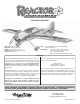
INSTRUCTION MANUAL Wingspan: 84.5 in [2140mm] Wing Area: 1556 in2 [100.4dm2] Weight: 14 – 17 lb [6350 – 7710g] Wing Loading: 21 – 25 oz/ft2 [63 – 77g/dm2] Length: 85 in [2160mm] Radio: 5-channel minimum computer radio with mixing functions, eight servos Motor/Engine: 1.60 – 2.10 cu in [26 – 34cc] two-stroke, 2.00 – 2.20 cu in [33 – 36cc] four-stroke, 2.5 – 3.0 cu in [43 –50cc] gas RimFire™ 80-75-230 out-runner brushless motor WARRANTY Great Planes® Model Manufacturing Co.
TABLE OF CONTENTS INTRODUCTION INTRODUCTION .................................................................... 2 AMA ....................................................................................... 2 SAFETY PRECAUTIONS ...................................................... 2 DECISIONS YOU MUST MAKE ............................................. 3 Gas Engine Option & Required Parts ............................... 3 Glow Engine Option & Required Parts..............................
❏ ❏ ❏ ❏ 5. If you are not an experienced pilot or have not flown this type of model before, we recommend that you get the assistance of an experienced pilot in your R/C club for your first flights. If you’re not a member of a club, your local hobby shop has information about clubs in your area whose membership includes experienced pilots. (4) 1/4-20 x 1-1/2" [38mm] SHCS (for DA-50) (4) 1/4" [6.4mm] Washers (4) 1/4" [6.4mm] Lock washers (4) 1/4-20 Blind nuts Glow Engine Option & Required Parts 6.
❏ ❏ ❏ ❏ ❏ ❏ ❏ ❏ ❏ ❏ ❏ ❏ We provide several places to mount your radio equipment based on the engine type. The servo extension lead lengths we recommend will allow you to mount your radio in all of the positions suggested in this manual. If you know that your radio equipment is to be mounted in the aft equipment tray, you may choose shorter servo leads for the tail and eliminate the 6" [152mm] leads we recommend for the inboard aileron servos.
Mail parts orders and payments by personal check to: 30-minute epoxy is specified it is highly recommended that you use only 30-minute (or 45-minute) epoxy, because you will need the working time and/or the additional strength. Hobby Services 3002 N. Apollo Drive, Suite 1 Champaign, IL 61822 • Be certain to specify the order number exactly as listed in the Replacement Parts List. Payment by credit card or personal check only; no C.O.D. Photos and sketches are placed before the step they refer to.
KIT INSPECTION Before starting to build, take an inventory of this kit to make sure it is complete and inspect the parts to make sure they are of acceptable quality. If any parts are missing or are not of acceptable quality, or if you need assistance with assembly, contact Product Support. When reporting defective or missing parts, use the part names exactly as they are written in the Kit Contents list.
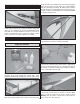
The tip should be 1/2" [13mm] from the rib. Test fit six-point type hinges into the wing so that the hinge pin is aligned with the hinge line. Deflecting each hinge 90° will help you determine when the hinge pin is parallel with the hinge line. If the hinge is too tight, you may use your hobby knife or a 5/32" [4mm] drill bit to carefully enlarge the hole. PREPARE FOR ASSEMBLY ❏ Lay out all of your covered parts like the fuselage, wings, and control surfaces.
Install the Aileron Servos To get the best performance from your Reactor, we recommend that you use four Futaba 9155 digital servos. These precision servos have the right amount of torque (153 oz-in [11 kg-cm]) and will give you the best control. As a budget alternative you can use a metal geared servo with a minimum 100 oz-in [7.2 kg-cm] torque rating but you should expect a slower response and some control blow-back at higher speeds.
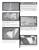
Assemble the Pushrods In this section you will build the aileron pushrods as well as the elevator and rudder pushrods. We’ll start with the four identical aileron pushrods and finish with the others which you can set aside to be used later. For this section you’ll need to have some silver solder and liquid silver-solder flux. We recommend using the Stay-Brite silver soldering kit (STAR2000). ❏❏ 3. Starting with the outboard servo bay, tie the guide string to the 24" [610mm] servo lead extension.
Install the Control Horns ❏❏ 4. Use a hobby torch to heat both the clevis and the pushrod. Apply silver solder to the joint. The heat of the clevis and the pushrod should melt the solder, not the direct flame of the torch. ❏ 1. Use your radio to center your aileron servos. Attach a 1-1/2" [38mm] single-sided servo arm (GPMM1105) to each servo so that the arm is parallel with the hinge line when the servo is centered. Install the arms so that they point outward toward the wing tip. ❏ ❏ 5.
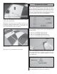
BUILD THE FUSELAGE Main Landing Gear Installation ❏ 1. Locate the 3/16" x 2" [4.8 x 51mm] axles, four 3/16" [4.8mm] wheel collars, four set screws, two axle nuts, and the two main wheels. File flat spots in the axle in the locations shown above. ❏❏ 3. Center a control horn over the line that you made, making sure that the clevis holes are also centered over the hinge line. Hold the horn in position and use a 1/16" [1.6mm] drill bit to drill four 1/2" [13mm] deep holes in the aileron.
❏ 5. Attach the axles to the main landing gear legs using the ❏ 8. Attach the wheel pants to the landing gear legs using self-locking axle nut. four 4-40 x 1/2" [13mm] SHCS, four split ring lock washers, and four #4 washers. Use threadlocking compound on the screw threads. Install the Horizontal Stabilizer ❏ 6. Trim the covering from the main landing gear slots in the fuselage. ❏ 1. Start by trimming the covering from the horizontal stabilizer slot in the fuselage.
❏ ❏ 3. Holding the stab in position, use a fine-point, felt-tip marker to trace lines onto the stab. Don’t forget to trace lines on the bottom side of the stab, too. 6. Temporarily install the wings onto the fuselage using the wing tube and the plastic 1/4-20 x 1" [25mm] wing bolts. Fit the stab once again and check the alignment of the stab with the wings by leveling the wings with your work surface and then measuring the distance between that and the tips of the stab.
Hinge the Horizontal Stabilizer This section details the process for hinging the elevators. We performed the operation using 30-minute epoxy. This is generally enough time to do both elevators with one batch if you are completely prepared. If you are worried about accomplishing both sides, or you are working in a warm climate, do one elevator at a time. ❏ 4. Fit the hinges into the stab, making sure to orient them so that the hinge pin is parallel to the hingeline. ❏ 1.
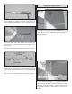
❏ 3. Use 30-minute epoxy to glue your hinges in place. Remember to align them and to deflect the rudder both ways when you install it. ❏ 2. Trim the covering from the elevator and rudder servo bays on the left side of the fuselage. ❏ 4. Use tape to hold your rudder in place while the epoxy cures. Install the Elevator & Rudder Servos ❏ 3. Attach a 36" [914mm] servo lead extension to the three tail servos.
❏ 5. Install the elevator and rudder servos. Use a 1/16" [1.6mm] ❏ 3. Center a control horn over the line that you made making sure that the clevis holes are also centered over the hinge line. Hold the horn in position and use a 1/16" [1.6mm] drill bit to drill four holes in the elevator. Remember to only drill 1/2" [13mm] deep. drill bit to drill the holes and use thin CA to harden the wood. ❏ 4. Use four #4 x 1/2" [13mm] sheet metal screws to mount the elevator control horns.
❏ 7. Install the 5-1/4" [133mm] pushrod to the left elevator servo and elevator. ❏ 4. Fit the tail gear assembly into the bushing and fit the tail gear retainer to the fuselage bottom as shown. Drill two 1/16" [1.6mm] holes into the fuselage using the retainer as a guide. Remove the tail gear assembly. ❏ 8. Install the 7-1/4" [184mm] pushrod onto the right elevator servo and elevator. Tail Gear Installation ❏ 5. Use the two 8mm sheet metal screws to attach the retainer to the fuselage. ❏ 1.
❏ 8. Adjust the tail gear’s position in the main bushing so that the tail gear wire is 1/2" [13mm] from the bottom of the fuselage. Use threadlocking compound on the set screw and tighten the collar. ENGINE/MOTOR INSTALLATION ❏ 2. Locate two 2-56 threaded ball links and two 2-56 hex In this section we cover the installation of the Desert Aircraft DA-50 gasoline engine, the O.S. 1.60 FX two-stroke glow engine, and the Great Planes ElectriFly 80mm brushless out-runner motor.
❏ 8. Locate the 2-56 x 36" [914mm] threaded one end rod. Measure 6" [152mm] from the unthreaded end and make a mark. Cut the wire at the mark and retain this portion. This will be referred to as “pushrod B.” The remaining portion of the rod will be used for the throttle later. ❏ 5. Cut a 1" [25mm] piece of outer pushrod tubing from the 36" [914mm] length supplied. Install it in the firewall as shown so that 1/4" [6.4mm] of the tube protrudes forward from the firewall.
threadlocking compound to the screw threads and install the 4-40 nut using a #4 washer and lock washer. ❏ 16. Locate the switch plate that fits your brand of radio switch. Four plates are supplied: two Futaba switch & Ernst charge jacks and two Hobbico heavy-duty & Ernst charge jacks. Fit your switch and charge jack to the plate and use a pen or pencil to draw an outline of the switch and jack onto the back side of the plate. Remove the switch and charge jack. ❏ 13.
❏ 20. Trim the covering from over the switch plate holes and install the ignition switch and charge jack. ❏ 23. Wrap your ignition module in 1/4" [6.4mm] thick R/C latex foam rubber. Mount the ignition module to one of the uprights or to the forward compartment floor using one of the straps that you made. ❏ 24. Wrap the ignition battery in latex foam rubber. Mount the battery using the other strap that you made. ❏ 21. Wrap the shielded spark plug lead of the igniter unit with electrical tape.
❏ 29. Build up the fuel tank stopper as shown and fit the fuel tubes. Solder the fuel line barbs in place. ❏ 26. Turn the model over. Wrap a tie wrap around the spark plug lead to make a “P” clamp. Route the spark plug lead in a fashion that keeps it away from the muffler. Use a spare servo screw to attach this to the side wall of the exhaust box. Since a screwdriver won’t fit, we suggest using a 1/4" [6.4mm] socket with a #1 Phillips bit. ❏ 30.
Tape it in place and use a 3/16" [4.8mm] drill bit to drill four engine mount holes on the firewall for the supplied engine mount. A center punch or scratch awl can be used to make a centering mark before you drill. ❏ 2. If you are using the O.S. 1.60 FX two-stroke engine, drill the hole for the throttle rod marked on the template. Use a 3/16" [4.8mm] drill bit for this. ❏ 33. Fit fuel lines to the tank and install it using the two straps you made. Route the fuel feed line to the carburetor.
beams. Position the engine on the mount so that the drive washer is 7-1/4" [184mm] from the firewall. Clamp the engine in this position. Drill and tap your engine mount using an 8-32 tap set. Install the engine to the mount using four 8-32 x 1" [25mm] socket head cap screws (SHCS), four #8 lock washers, and four #8 washers. ❏ 8. Trim the plastic pushrod tube so that there is at least 1/4" [6.
onto the pushrod tube from inside the fuselage. Note: The base of each standoff can be trimmed down for a custom fit. line pointing to the top of the tank. You may want to use a felt-tip pen to mark which direction the vent line is pointed so that you know where the top of the tank is. ❏ 12. Slide the pushrod into the plastic tube and connect the clevis to your throttle arm. Slide the other end of the pushrod into the screw-lock pushrod connector.
Tape it in place and use a 9/32" [7.1mm] drill bit to drill four motor mount holes on the firewall for the Great Planes 80mm Standoff Mount. A center punch or scratch awl can be used to make a centering mark before you drill. Note: The Great Planes 80mm RimFire Standoff Mount set (GPMG1275) is available separately. ❏ 19. Turn the model over. Use epoxy to glue the fuel filler mount to the exhaust tunnel. Use sandpaper to roughen the surface of where the fuel filler mount will adhere to. ❏ 20.
❏ 6. Use 80-grit sandpaper to roughen up the coated surface of the firewall and the equipment tray where the ESC tray will mount. Use epoxy to bond the ESC tray to the fuselage as shown. A piece of triangle stock is supplied to help secure the tray to the firewall. ❏ 4. Locate four 50mm, 20mm, and 10mm standoff spacers as well as eight mounting feet, four 1/4-20 x 5" [127mm] bolts, four flat washers, and four lock washers. Install the motor using these parts as shown. ❏ 7.
RADIO INSTALLATION Radio System Installation – Gas Engine ❏ 1. Prepare an ignition switch plate as you did earlier. ❏ 5. Locate the aft equipment tray, the tray doubler and the two side rails. Glue the tray doubler to the bottom of the tray. Align the tabs on each rail with the corresponding slots in the fuselage and glue each rail in place as shown. ❏ 2. Install the ignition switch plate on the model using epoxy. A cutout for the switch plate is provided in the left and right rear fuselage.
❏ 10. Install a servo arm. Set your throttle servo to the fullthrottle position and connect the pushrod. ❏ 7. Install the throttle servo in the aft tray. Drill four 1/16" [1.6mm] holes and harden them with thin CA. Note the position of the servo output shaft. ❏ 11. Locate one nylon ball link socket and one 2-56 x 1" [25mm] threaded rod. Thread the rod into the ball link socket. ❏ 8. Locate the wood pushrod standoffs. Fit them to the gray outer pushrod tube and install the tube.
❏ 13. Position and glue the pushrod standoffs and the outer pushrod tube in place. ❏ 16. Wrap your receiver and battery pack with 1/4" [6.4mm] thick latex foam. Use the straps you made to mount your battery and receiver to the aft equipment tray. ❏ 17. Connect the battery to the switch. Use heat shrink tubing to secure the connection between the battery and the switch. ❏ 14. Locate the non-adhesive backed hook and loop material.
Radio System Installation – Glow Engine ❏ 5. Trim the covering from over the switch plate holes and install the switch and charge jack. ❏ 1. Locate the switch plate that fits your brand of radio switch. Four plates are supplied: two Futaba switch & Ernst charge jacks and two Hobbico heavy-duty & Ernst charge jacks. Fit your switch and charge jack to the plate and use a pen or pencil to draw an outline of the switch and jack onto the back side of the plate. Remove the switch and charge jack. ❏ 6.
❏ 2. Use two 7 x 22mm and two 6 x 29mm sticks to make a flange for the charge plate. ❏ 9. Wrap your receiver and battery pack with 1/4" [6.4mm] thick latex foam. Use the straps you made to mount your battery and receiver to the center equipment tray. ❏ 10. We used a 2.4GHz radio system for this build-up, but if ❏ you’re using a 72MHz radio system, an antenna routing tube is provided for you in the upper left side of the fuselage. 3. Install the switch plate on the model using epoxy. For C.G.
❏ 8. Locate the non-adhesive backed hook and loop material. Make two sets of straps for your receiver and battery by joining a piece of “hook” material to a piece of “loop” material. ❏ 6. Locate the aft equipment tray and the two side rails. Align the tabs on each rail with the corresponding slots in the fuselage and glue each rail in place as shown. ❏ 9. Connect a Y-connector to each aileron channel. Connect the other servo leads, the battery switch, and your ESC signal lead to your receiver. ❏ 7.
FINAL ASSEMBLY Cowl & Prop Installation The following cowl installation instructions cover the DA-50 gasoline engine. Trimming the cowl to fit other engines may require modification of these procedures, but the basic idea is the same. For the DA-50 or similar gas engines, a template is provided in the back of this manual so that the engine does not have to be removed. Other engine installations may require removal of the engine while leaving the paper templates in place.
❏ 3. Remove the muffler while leaving the template in place. ❏ 6. Fit the cowl centering tool to the cowl as shown. Use only two small drops of medium CA to tack the inside and the outside pieces together so that you can remove them easily later. ❏ 4. Locate the wood parts shown. ❏ 7. Fit the cowl to the plane so that the cowl centering tool bottoms out on the engine’s drive washer. Position the paper template and trace the muffler cutout onto the cowl using a felttip pen. ❏ 5.
Wing Installation ❏ 9. Temporarily fit the canopy and hatch. Fit the cowl once again, making sure to slide it back until the centering tool contacts the drive washer. Use a 1/16" [1.6mm] drill bit to make four 1/2" [13mm] deep holes in the fuselage sides (two per side). Drill them so that they are 1/2" [13mm] from the rear edge of the cowl. Apply thin CA to the holes to harden the wood. ❏ 1.
GET THE MODEL READY TO FLY Canopy Installation Check the Control Directions ❏ 1. Turn on the transmitter and receiver and center the trims. If necessary, remove the servo arms from the servos and reposition them so they are centered. Reinstall the screws that hold on the servo arms using threadlocking compound. ❏ 2. With the transmitter and receiver still on, check all the control surfaces to see that they are centered. If necessary, adjust the clevises on the pushrods to center the control surfaces.
These are the recommended control surface throws: Set the Control Throws ELEVATOR: To ensure a successful first flight, fly your Reactor set up only according to the C.G. and control surface throws specified in this manual. The throws and C.G. are not arbitrary, but have been determined through extensive testing and accurate record-keeping. This provides you with the best chance for success and enjoyable first flights that should be surprise-free. Additionally, the throws and C.G.
PREFLIGHT Identify Your Model ❏ 2. With the wing attached to the fuselage, all parts of the No matter if you fly at an AMA sanctioned R/C club site or if you fly somewhere on your own, you should always have your name, address, telephone number and AMA number on or inside your model. It is required at all AMA R/C club flying sites and AMA sanctioned flying events. Fill out the identification tag on page 43 and place it on or inside your model.
Make sure that all electrical connections are soldered properly. Run the motor for a few minutes and then check the wires and connections for excessive heat. Hot connections may indicate poor solder joints. ENGINE & MOTOR SAFETY PRECAUTIONS Failure to follow these safety precautions may result in severe injury to yourself and others. Keep all engine fuel in a safe place, away from high heat, sparks or flames, as fuel is very flammable.
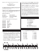
Batteries of different voltages, but not different capacities may also be connected in Series: Battery Precautions/Connecting Batteries These are three 11.1V, 3200mAh batteries and one 7.4V, 3200mAh battery. When joined in Series, the result will be a 40.7V, 3200mAh battery. This is how to connect four batteries in Series: 7.4V (3-cell) 3200mAh 18.5V 3200mAh 11.1V (3-cell) 3200mAh 40.7V 3200mAh 11.1V (3-cell) 3200mAh 22.2V 3200mAh 11.
❏ 3. proximity of full-scale aircraft. Where necessary, an observer shall be utilized to supervise flying to avoid having models fly in the proximity of full-scale aircraft. ❏ 3) Where established, I will abide by the safety rules for the flying site I use, and I will not willfully and deliberately fly my models in a careless, reckless and/or dangerous manner. ❏ 5) I will not fly my model unless it is identified with my name and address or AMA number, on or in the model.
air. At this moment it is likely that you will need to apply more right rudder to counteract engine torque. Be smooth on the elevator stick, allowing the model to establish a gentle climb to a safe altitude before turning into the traffic pattern. FLYING Fuel Mixture Adjustments Flight A fully cowled engine may run at a higher temperature than an un-cowled engine. For this reason, the fuel mixture should be richened so the engine runs at about 200 rpm below peak speed.
loop, check your altitude, mind the wind direction (anticipating rudder corrections that will be required to maintain heading), remember to throttle back at the top, and make certain you are on the desired rates (high/low rates). A flight plan greatly reduces the chances of crashing your model just because of poor planning and impulsive moves. Remember to think. begins to point downwards, reduce the throttle (to keep the model from being pulled downwards).
but make your adjustments smooth. Some right aileron may be needed to keep the model from torque rolling. Use the rudder and elevator to keep the nose pointing straight up. Be patient as this maneuver will take a while to learn. turn the model, simply input the elevator or rudder a little sooner or later in the rotation. It’s all a matter of timing. PINWHEEL TORQUE ROLL This is the same as the vertical hover but without the use of right aileron to keep the model from rolling.
COWL TRIMMING TEMPLATE Electric Installation Cutout Gasoline Engine Cowl Template 46
ENGINE MOUNTING TEMPLATES 47
ENGINE MOUNTING TEMPLATES