
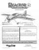
User Manual


Mail parts orders and payments by personal check to:
Hobby Services
3002 N. Apollo Drive, Suite 1
Champaign, IL 61822
Be certain to specify the order number exactly as listed in
the Replacement Parts List. Payment by credit card or
personal check only; no C.O.D.
If additional assistance is required for any reason contact Product
Support by e-mail at productsupport@greatplanes.com,
or by telephone at (217) 398-8970.
Replacement Parts List
Description How to Purchase
Missing pieces Contact Product Support
Instruction manual Contact Product Support
Full-size plans Not available
Contact your hobby supplier for the following parts:
GPMA3090 Fuselage
GPMA3091 Wing Set
GPMA3092 Cowl
GPMA3093 Wheel Pants
GPMA3094 Tail Surface Set
GPMA3095 Landing Gear
GPMA3096 Canopy
GPMA3097 Wing Tube
GPMA3098 Decal
GPMA3099 Spinner
IMPORTANT BUILDING NOTES
• When you see the term test fi t in the instructions,
it means that you should fi rst position the part on the
assembly without using any glue, then slightly modify
or custom fi t the part as necessary for the best fi t.
• Whenever the term glue is written you should rely upon
your experience to decide what type of glue to use. When
a specifi c type of adhesive works best for that step, the
instructions will make a recommendation.
• Whenever just epoxy is specifi ed you may use either
30-minute (or 45-minute) epoxy or 6-minute epoxy. When
30-minute epoxy is specifi ed it is highly recommended that
you use only 30-minute (or 45-minute) epoxy, because you
will need the working time and/or the additional strength.
• Photos and sketches are placed before the step they
refer to. Frequently you can study photos in following
steps to get another view of the same parts.
• The stabilizer and wing incidences and motor thrust
angles have been factory-built into this model. However,
some technically-minded modelers may wish to check
these measurements anyway. To view this information
visit the web site at www.greatplanes.com and click on
“Technical Data.” Due to manufacturing tolerances which
will have little or no effect on the way your model will fl y,
please expect slight deviations between your model and
the published values.
COMMON ABBREVIATIONS
Stab = Horizontal Stabilizer
Fin = Vertical Fin
LE = Leading Edge
TE = Trailing Edge
LG = Landing Gear
Ply = Plywood
" = Inches
mm = Millimeters
SHCS = Socket Head Cap Screw
ESC = Electronic Speed Control
METRIC CONVERSIONS
1" = 25.4mm (conversion factor)
1/64" = .4mm
1/32" = .8mm
1/16" = 1.6mm
3/32" = 2.4mm
1/8" = 3.2mm
5/32" = 4.0mm
3/16" = 4.8mm
1/4" = 6.4mm
3/8" = 9.5mm
1/2" = 12.7mm
5/8" = 15.9mm
3/4" = 19.0mm
1" = 25.4mm
2" = 50.8mm
3" = 76.2mm
6" = 152.4mm
12" = 304.8mm
18" = 457.2mm
21" = 533.4mm
24" = 609.6mm
30" = 762.0mm
36" = 914.4mm
5