�������������������
1. Table of Contents Table Of Contents 1 1. Important Information 2~3 2. Unit Description 4~5 3. Initial Setup 6~9 4. How to Splice Wires 10 5. Harness Diagram 11 6. Wiring Power, Ground, Airflow Meter, Throttle, RPM signal 12~13 7. VTEC / Idle Control Valve 14 8. Injector Wires 15 ~ 16 9. Ignition Signal Wire 17 ~ 18 10.Analog Input, Output, / Vehicle Speed Signal 19 11.Crank & Cam Angle / Water & Intake Temp, Knock Signal 20 12.NVCS / Relay Channels 21 13.
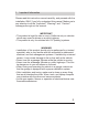
1. Important Information Please read this instruction manual carefully, and proceed with the installation ONLY if you fully understand this manual. Make sure to pay attention to all the "Important!" "Warning!" and "Caution!" messages through out the manual. IMPORTANT! • This product is legal for sale or use in California only on vehicles which may never be driven on a public highway. • This product is only for vehicles with 12V (battery) systems.
1. Important Information Caution! • Improper tuning of the e-Manage Ultimate can cause damage to the engine. • GReddy Performance Products, Inc. will not take any responsibility of damage caused by improper installation or tuning. • Tuning should be performed only by a technician who fully understands the vehicle’s fuel management and ignition timing requirement for the engine being tuned. • Always use a proper air/fuel ratio meter when tuning the e-Manage Ultimate.
4
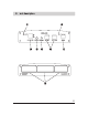
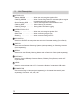
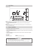
2. Unit Description ACTIVE L.E.D • Steady GREEN - - - - - - When the unit recognize Ignition ON • Flashing GREEN - - - - - When Fouled Plug feature is activated (When engine is started with wide open throttle) • Quick Flashing RED - - - - When Self Diagnostic has detected an error • Flashing RED - - - - - - - When Warning is activated • Flashing Orange - - - - - During Main Unit Data Logging INTERACTION L.E.D.
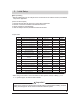
3. Initial Setup Jumper Setting • Before installing the unit, the Jumpers in the unit must be set for vehicle’s sensors, and desired maps for the application. (How to set the Jumpers) 1. Remove the rear panel by removing 4 screws with provided tool. 2. Remove 2 screws on the bottom and slide the board out. 3. Set the Jumpers for the application. 4. After the Jumpers are set, reinstall the board into the case. Jumper Chart Jumper No.
3. Initial Setup Jumper Setting Description JP1 Injector Input / Output Signal CH1 This jumper will configure the Injector Input / Output Signal CH1. Set to “OPEN” when using Injector Adj. Map to trim and add fuel, and set to “1-2” to add only. JP2 Injector Input / Output Signal CH2 This jumper will configure the Injector Input / Output Signal CH2. Set to “OPEN” when using Injector Adj. Map to trim and add fuel, and set to “1-2” to add only.
3. Initial Setup Jumper Setting JP11 OPTION 1 This jumper will configure the OPTION 1 port on the Front Panel of the unit. Set to “OPEN” for Normal type(when used for pressure or A/F sensor), and “1-2” when using GReddy Temp Sensor. JP12 OPTION 2 This jumper will configure the OPTION 2 port on the Front Panel of the unit. Set to “OPEN” for Normal type(when used for pressure or A/F sensor), and “1-2” when using GReddy Temp Sensor.
3. Initial Setup Jumper Location When Jumping “1-2” or “2-3” make sure to match the pin numbers printed on the circuit board at the coresponding jumper locations. For “OPEN” make sure the jumper is not jumping the pins at the corresponding jumper locations. When setting jumpers to “OPEN” make sure to place the jumper on to one side of the pin to prevent loosing the jumpers. 4. Before Installation 1. Disconnect the negative terminal of the battery. 2.
5. How to splice wires 1.Strip the wire as shown. 2.Wrap the stripped wire together as shown, and set the crimp in place. *Crimp is not neccessary if soldering. 3.Crimp or solder the connection. 6. 4.wrap the connection with shrink tube or electrical tape. How to install the connectors 1.Strip the end of the wire and slip the protective sleeve on. 2.Set the connector over the stripped end. 3.Crimp the inside part with proper crimping tool. 4.
8. Wiring Power, Ground, Airflow Meter,Throttle, RPM Signal Hot-wire airflow meter, Flap type airflow meter, or Pressure sensor Gray (Throttle signal) White (Airflow Input 1) Connector B × Green (Airflow Output) Brown (rpm signal) Black (ECU Ground) Red (12v IG power) Female connector ECU (Engine Control Unit) Male connector Splice * Always use the provided connectors or solder all connections.
8. Wiring Power, Ground, Airflow Meter,Throttle, RPM Signal for RB26DETT (with 2 airflow meters) Gray (Throttle signal) White (Airflow Input 1) Yellow (Airflow Input 2) Connector B ×× Green (Airflow Output) Brown (rpm signal) Black (ECU Ground) Red (12v IG power) Female connector Male connector ECU (Engine Control Unit) Splice * The 2 wires for the airflow meter on the ECU will be connected together to the Airflow Output wire. * Make sure the jumper JP10 is set to “1-2” in the unit.
9.
10. Injector Signal Wires • Wire the injector signal wires for each cylinders. (except for Rotary Engines). • Normally, the Injector Adjustment will be set to add & trim (jumper JP1~6, 18 set to “OPEN”. Inj Adj. Map will be used to add and trim fuel). This can be set for add only. (jumper JP1~6, 18 set to “1-2”. Inj Adj.
10. Injector Signal Wires When changing I/J CH Example: Changing group injection to sequential injection Female connector ECU (Engine Control Unit) Male connector How to connect • Connect the necessary I/J CH OUT wires to the Connector C. • The I/J CH Setting must be configured with PC before starting the engine. • Confirm the injector wiring to match the injection method.
11. Ignition Signal Wire • Connect the e-manage Ignition channels in the engine’s firing order shown in the chart below.
11. Ignition Signal Wire Distributer Type Ignition Honda Distributer (with 2 signal) 26 pin connector Female Connector ECU (Engine Control Unit) Male Connector Splice Blue/White (IG CH-1 IN) Connector A Blue/White (IG CH-1 IN) ×× Blue/Black (IG CH-1 OUT) *On Honda EG type vehicles, there are 2 ignition signals in the 26 pin connector. Group the 2 together as shown above.
12. Analog Input, Output / Vehicle Speed Signal Analog Input, Output wiring •These channels can be used on vehicels with airflow meter that uses a map sensor for boost limiter. (Factory contorlled boost cut or fuel cut) •Connect this wire to throttle or accelerator position sensor input, to change feedback range or A/T shift schedule. Female Connector Male Connector ECU (Engine Control Unit) •Pay close attention to the input and output wiring order (direction).
13. Crank & Cam Angle / Water & Intake Temp, Knock Signal Crank Angle Signal & Cam Angle Signal • Connect these wires for e-manage Ultimate to recognize the rpm signal from crank and cam angle signal if there are no tach signal out put from the ecu. Also. by connecting these wires Ignition timing can be monitored in the data log feature.
14. NVCS / Relay Channels NVCS (Nissan Valve Control System) •Connecting one of these channels to the NVCS solenoid to control the NVCS. ECU (Engine Control Unit) Cut and tape up Connector B Connect to desired channel NVCS Solenoid •Make sure the wire that was cut is taped up to prevent any short. •When using this feature the proper channels must be configured in the “I/J” set up in the Parameter setting in the software and make the necessary jumper setting to activate these channels.
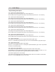
15. ECU Location Chart Channel Symbol Description Power Crank Angle Signal RPM & Ignition Signal Ground Cam Angle Signal RPM Signal Intake Temp Siganl Throttle Signal Water Temp Signal No. & No. Ignition Signal No. Leading Ignition Signal (F : front, C : Center, R : Rear) Airflow/map Sensor Signal No. VTEC Signal Absolute Pressure Sensor Siganl VTM Signal Vehicle Speed Signal Sensor Ground No. Injector Signal No. Ignition Signal Knock Signal No.
16.
16.
16.
16.
16.
16.
16.
16.
16. ECU Wire Location Chart MITSUBISHI Model Chassis Code Year Engine Code Sensor Type CP # ECU Location LANCER 3000GT ECLIPSE / (2.4L) / D53 M/T D53 A/T (3.
16.
16.
16.
16.
16.
Notes 37
Notes 38