Fan Selection Application-Based Selection Performance Theory
SELECTING THE RIGHT FAN FOR THE JOB This book is designed to help you select the fan that will best fit the application for which it is intended. With the large number of different fan types and sizes available it's necessary to know which fan model does the best job in certain applications and then be able to select the most economical fan size for the job. With that in mind, this guide is constructed in three sections.
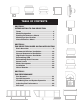
TABLE OF CONTENTS SECTION 1 INTRODUCTION TO FAN SELECTION Terms . . . . . . . . . . . . . . . . . . Model Designation . . . . . . . . Reading Performance Charts Matching a Specification . . . Cross Reference Chart . . . . . . . . . . . . . . . . . . . . . . . . . . . . . . . . . . . . . . . . . . . . . . . . . . . . . . . . . . . . . . . . . . . . . . .4 .4 .5 .7 .8 SECTION 2 FAN SELECTION BASED ON FAN APPLICATION Basic Overview. . . . . . . . . . . . . . Commercial Kitchen Ventilation .
INTRODUCTION TO FAN SELECTION This is the first and most basic of this manual’s three sections, all of which are designed to enable you to select the right fan for the job. Look at this first section as a “user’s manual” for Greenheck literature.
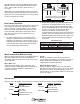
Reading Performance Charts The most important part of selecting a fan is the ability to read the performance charts. Most of the performance charts in the catalog are similar and are read in the same manner. Models RSF and BCF are exceptions to this rule. The selection procedure for these models is handled separately. Direct drive and belt drive fans are also addressed separately. Belt Drive Selection Assume that a job requires a belt drive roof exhauster to move 1000 cfm against 0.25 in. Ps.
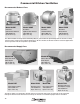
One advantage of choosing the GB-101-4-R2 over the GB-101-4-R1 is that it is capable of running at higher rpm’s, which enables the fan to move more air if necessary. Motor pulleys are adjusted by loosening the set screw and turning the top half of the pulley (see illustrations at right). This causes the pulley diameter to change, which results in changing the fan rpm. Belt Opening the pulley decreases fan rpm. Closing the pulley increases fan rpm.
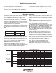
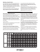
Matching a Specification There will be times when a Greenheck model will have to be matched to a competing manufacturer’s unit. To aid in these circumstances, we have provided a cross reference chart which includes our nine most common competitors. If the manufacturer you need is not on this chart, contact Greenheck for assistance. To use the cross reference chart, on next page, start with the manufacturer at the top. Then follow down until the model in question is found.
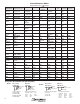
Cross Reference Chart (Models in italics refer to older models) Greenheck Jenn Cook Penn Updated 12-7-2004 G ACED Domex DX CE,CX,CH C-D,CVD,TCD XQ,XR,AT,AW GB ACEB Domex DXB CDE, CBX C-B,TCB,UCB KB,JB,MB,AB,LB CUE CUBE ACRUD, VCRD ACRUB,VCR Fumex FX Fumex FXB UCBE,UCBH URB,R-B,BTD CW ACWD SW,GW Acme PRN Carnes (Breidert) (Stanley) CRD VEDK COOLAIR AirMaster Captive Aire (ILG) CRD CDD VEDB,VEDC PN,PNN,PV NBCR (Chelsea) (Flow Air) DR RDD VEBK CRB CBD BCR VEBC LSB
FAN SELECTION BASED ON FAN APPLICATION Basic Overview Ventilating a building simply replaces stale or foul air with clean, fresh air. Although the ventilation process is required for many different applications, the airflow fundamentals never change: Undesired air out, fresh air in The key variables that do change depending on applications are the fan model and the air volume flow rate (cfm).
Commercial Kitchen Ventilation Recommended Exhaust Fans Model CUBE Model USGF Model CWB Model SWB Belt Drive Upblast Roof Exhaust 300-30,000 cfm Up to 5.0 in. wg Belt Drive Upblast Roof Exhaust 300-7,000 cfm Up to 3 in. wg Belt Drive Sidewall Exhaust 300-12,000 cfm Up to 2.75 in. wg Belt Drive Utility Blower 500-30,000 cfm Up to 5.0 in.
Commercial Kitchen Ventilation This drawing shows a commercial kitchen with a typical kitchen ventilation system consisting of a roof mounted CUBE upblast exhaust fan and a Model RSF supply fan. Exhaust fan variations include the model CWB sidewall exhaust fan (also shown) when penetrating the roof is not practical. The Model SWB utility blower is recommended when higher static pressure capability is required to pull exhaust through long duct runs (typically 3 stories or more).
General Commercial Ventilation Model G Model CW Direct Drive Roof Exhaust 90-3,200 cfm Up to 1.0 in. wg Direct Drive Wall Exhaust 80-6,000 cfm Up to 2.25 in. wg Model GB Model CWB Belt Drive Roof Exhaust 80-44,700 cfm Up to 3.25 in. wg Belt Drive Wall Exhaust 300-12,000 cfm Up to 2.75 in. wg The above models are designed for exhausting relatively clean air at temperatures up to 130°F. Motors are out of the airstream.
Typical Commercial Ventilation Installations 13
General Industrial Ventilation Model SB Belt Drive Propeller Sidewall 3,600-85,000 cfm Up to 1.0 in. wg Model RBU Belt Drive Propeller Upblast 4,000-65,000 cfm Up to 1.0 in. wg Model RBUMO Belt Drive Propeller Upblast 3,000-60,000 Up to 1.0 in. wg Model RB RBS-Supply RBE-Exhaust RBF-Filtered Belt Drive Propeller Roof 2,000-86,500 cfm Up to 1.5 in. wg Typical Applications Propeller fans are ideal for ventilating high air volumes at low static pressures (0.50 in. or less).
High Static Pressure Ventilation Model SWB Belt Drive Utility Blower 500-30,000 cfm Temperatures up to 400°F Up to 5.0 in. wg Model BSQ Belt Drive Inline Fan 150-28,000 cfm Temperatures up to 180°F Up to 4.0 in. wg Typical Applications Models SWB and BSQ are general, all-purpose fans that are capable of moving high air volumes against high static pressures (up to 5.0 in wg). High static pressures are generated by long or complex duct systems, especially when capture hoods are present.
Determining CFM (cfm) climates and heavier than normal area usage, select a lower number in the range to change the air more quickly. For moderate climates with lighter usages, select a higher number in the range. After the model is known, the cfm must be determined. Consult local code requirements or the table below for suggested air changes for proper ventilation. The ranges specified will adequately ventilate the corresponding areas in most cases.
Determining Static Pressure (Ps) The pressures generated by fans in ductwork are very small. Yet, accurately estimating the static pressure is critical to proper fan selection. Exhaust Fan Fan static pressure is measured in inches of water gauge. One pound per square inch is equivalent to 27.7 in. of water gauge. Static pressures in fan systems are typically less than 2 in. of water gauge, or 0.072 Psi. The drawing to the right illustrates how static pressures are measured in ductwork with a manometer.
Preliminary Selections At this point we know the model, cfm and Ps. With this information we can refer to the GB performance charts to determine the sizes available to move 2400 cfm against 0.50 in. Ps. In our case, all of the criteria can be met by more than one size of a particular model. When this occurs, choose the size that provides the greatest airflow range about the desired cfm. For example, many direct drive fans have three speeds. If possible, choose a size that uses the middle rpm.
Sound Levels In many cases, the sound generated by a fan must be considered. For the fan industry, a common unit for expressing sound pressure level is the sone. In practical terms, the loudness of one sone is equivalent to the sound of a quiet refrigerator heard from five feet away in an acoustically average room. Suggested Limits for Room Loudness Sones DBA 1.3-4 32-48 Private homes (rural and suburban) 1.
Installation To ensure proper fan performance as cataloged, caution must be exercised in fan placement and connection to the ventilation system. Obstructions, transitions, poorly designed elbows, improperly Uniform Flow selected dampers, etc., can cause reduced performance, excessive noise, and increased mechanical stressing. For the fan to perform as published, the system must provide uniform and stable airflow into the fan.
FAN PERFORMANCE The first two sections of this guide contain information needed to select the right fan for the particular application. The information in this section is useful once the fan has been selected and installed on the job. The fan curves and system resistance curves below will help to solve fan performance problems that may be encountered in a variety of applications. Fan Dynamics A fan is simply an air pump. The rate at which a fan can “pump” air depends on the pressure the fan must overcome.
System Resistance Curve Varying System Resistance Curve Sample problem: If a system is designed to move 1000 cfm at a resistance of 0.25 in. Ps, what static pressure would the fan have to overcome to produce 2000 cfm of airflow? Solution: Since static pressure varies as the square of cfm, we can solve for the new Ps (Ps2 ) with the following equation: Ps2 = Ps1 x 2 2000 c f m = 0.25 in. x ( = 1.0 in.
Operating Point The operating point of the fan and the system is the point where these two curves intersect. This intersection will determine the cfm and Ps delivered. Adjusting Fan Performance Varying Operating Points There is a direct relationship between cfm and rpm within a system. Doubling the fan rpm will double the cfm delivered. Sample problem: The figure on page 21 showed a fan curve at 700 rpm which had an operating point of 1000 cfm at 0.25 in. Ps.
Fan Laws In a steady-state system, as the fan rpm changes, cfm, Ps and BHp (horsepower) also change. The equations below, known better as fan laws, show the relationship between these performance parameters. cfmNew = rpmNew x cfmOld rpmOld ( rpm PsNew = rpm New Old 2 ) x Ps rpm BhpNew = rpm New Old ( Old 3 ) x Bhp Old The first two equations have already been covered in the fan and system dynamics section. Refer to the examples in those sections on how to apply these equations.