
Operation Manual

9
English (original instructions)
FR
EN
FR DE ES IT PT NL SV DA NO FI
DE
FR EN ES IT PT NL SV DA NO FI
ES
FR EN DE IT PT NL SV DA NO FI
IT
FR EN DE ES PT NL SV DA NO FI
PT
FR EN DE ES IT NL SV DA NO FI
NL
FR EN DE ES IT PT SV DA NO FI
SV
FR EN DE ES IT PT NL DA NO FI
DA
FR EN DE ES IT PT NL SV NO FI
NO
FR EN DE ES IT PT NL SV DA FI
FI
FR EN DE ES IT PT NL SV DA NO
HU CS RU RO PL SL HR
HU CS RU RO PL SL HR
HU CS RU RO PL SL HR
HU CS RU RO PL SL HR
HU CS RU RO PL SL HR
HU CS RU RO PL SL HR
HU CS RU RO PL SL HR
HU CS RU RO PL SL HR
HU CS RU RO PL SL HR
HU CS RU RO PL SL HR
ET LT LV SK BG
ET LT LV SK BG
ET LT LV SK BG
ET LT LV SK BG
ET LT LV SK BG
ET LT LV SK BG
ET LT LV SK BG
ET LT LV SK BG
ET LT LV SK BG
ET LT LV SK BG
FR EN DE ES IT PT NL SV DA NO FI
FR EN DE ES IT PT NL SV DA NO FI
FR EN DE ES IT PT NL SV DA NO FI
FR EN DE ES IT PT NL SV DA NO FI
FR EN DE ES IT PT NL SV DA NO FI
FR EN DE ES IT PT NL SV DA NO FI
FR EN DE ES IT PT NL SV DA NO FI
HU
CS RU RO PL SL HR ET LT LV SK BG
CS
HU RU RO PL SL HR
RU
HU CS RO PL SL HR
RO
HU CS RU PL SL HR
PL
HU CS RU RO SL HR
SL
HU CS RU RO PL HR
HR
HU CS RU RO PL SL
ET LT LV SK BG
ET LT LV SK BG
ET LT LV SK BG
ET LT LV SK BG
ET LT LV SK BG
ET LT LV SK BG
FR EN DE ES IT PT NL SV DA NO FI
FR EN DE ES IT PT NL SV DA NO FI
FR EN DE ES IT PT NL SV DA NO FI
FR EN DE ES IT PT NL SV DA NO FI
FR EN DE ES IT PT NL SV DA NO FI
HU CS RU RO PL SL HR
HU CS RU RO PL SL HR
HU CS RU RO PL SL HR
HU CS RU RO PL SL HR
HU CS RU RO PL SL HR
ET
LT LV SK BG
LT
ET LV SK BG
LV
ET LT SK BG
SK
ET LT LV BG
BG
ET LT LV SK
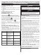
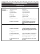
SPECIFICATIONS
Product Specifications
Model
24227
Motor
Air Velocity
Weight (Battery
Pack not included)
Battery Pack
Charger
DESCRIPTION
1. Variable switch
2. Low/high button
3. ON/OFF button
4. Auxiliary handle
5. Mulch/vacuum gate
6. Lock button
7. Blower tube
8. Concentrator nozzle
9. Mulcher tubes
10. Bag
11. 40V lithium-ion battery
For complete charging instructions, refer to the
Operator’s Manuals for your battery pack and
charger models.
NOTE: To avoid serious personal injury, always remove
the battery pack and keep hands clear of the variable
speed trigger when carrying or transporting the tool.
TO INSTALL BATTERY PACK
See Figure 5.
■ Place the battery pack in the blower. Align raised rib
on battery pack with grooves in the blower’s battery
port.
■ Make sure the latch on bottom of the battery pack
snaps in place and that battery pack is secured in the
blower before beginning operation.
CAUTION
When placing battery pack in the blower, be sure the
raised ribs on the battery pack align with the grooves
in the top of the blower. Make sure the battery is fully
seated, and it latches into place properly. Improper
installation of the battery pack can cause damage to
internal components.
40Volt DC
280 km/h(Max)
4.84 kg
29727
29417 / 29447
12. Notched area
13. Air outlet
14. Slot
15. Tab
16. Strap
17. Latch
18. Rib
ASSEMBLY
UNPACKING
■ Carefully remove the product and any accessories
from the box.
■ Inspect the product carefully to make sure no breakage
or damage occurred during shipping.
■ Do not discard the packing material until you have
carefully inspected and satisfactorily operated the
product.
■ If any parts are damaged or missing, please call your
Greenworks Tools service centre for assistance.
The blower vac is supplied with some components not
assembled. To assemble these, proceed as follows:
ASSEMBLE AS A MULCHER(Fig.2)
■ Slide the front and rear mulcher tubes together until
locked. (See fig 2)
■ Pull the lock button forward to disengage the gate.
Hold the gate open. (See fig 2.1)
■ Insert the “wedged” end clip of the mulcher tube into
the rear clip. (See fig 2.2). Push the “hooked” end clip
of the mulcher tube into the front clip. (See fig 2.3).
Press the lock button back to engage the mulcher
tube. (See fig 2.4)
■ To remove mulcher tubes, follow the steps (3) (2) (1).
■ Insert the bag adaptor into the blower outlet. Lock the
bag adaptor with the lock button. To remove the bag,
simply press lock button and remove bag. (see Fig.4).
NOTE: It may be necessary to remove the blower tube or
mulcher tubes to clear a blocked tube or impeller.
WARNING:
To
prevent serious personal injury,
make sure the
switch is in the OFF position, it is unplugged, and
the impellers have stopped before attaching or
removing tubes.
ASSEMBLE AS A BLOWER(Fig.3)
■
■
Slide blower tube forward until the notched areas on
the blower housing click into the slots on the tube.
INSTALLING BAG WITH SHOULDER HARNESS (Fig. 4)
■ While standing in the operating position adjust the
length to fit the operator’s size. Pull the tab to lengthen,
pull the strap to shorten.
Insert the concentrator nozzle into the regular nozzle
to lock. (Concentrator nozzle is used to increase air
flow in tight areas: flower beds,under decks, etc)