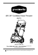
40V 20'' Cordless Snow Thrower 26272 Owner’s Manual TOLL-FREE HELPLINE: 1-888-90WORKS (888.909.6757) www.GreenWorksTools.com Read all safety rules and instructions carefully before operating this tool.
CONTENTS Contents............................................................................................................................... 2 Product specifications........................................................................................................... 2 Safety information..............................................................................................................3-5 Symbols..............................................................................................
SAFETY INFORMATION FOLLOW THESE RULES WHILE OPERATING THE SNOW THROWER I M P O R TA N T READ AND UNDERSTAND ALL INSTRUCTIONS. Failure to follow all instructions listed below may result in electric shock, fire, and/or serious personal injury. • Walk. Do not run. • Verify that the snow thrower is not in contact with anything before turning it on. • Stay away from the discharge chute and impeller openings at all times. Keep face, hands, and feet away from concealed, moving, or rotating parts.
SAFETY INFORMATION • Do not attempt to clear the impeller while the motor is running. • Keep clothing and body parts away from the impeller. • Stop the motor when stopped or when moving from one location to another. • Remove the battery pack when it is being transported and when it is not in use. • After striking a foreign object, turn the snow thrower off and remove the battery pack, and then inspect it for damage. Repair any damage before restarting and using the snow thrower.
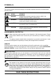
SAFETY INFORMATION C A U T I O N USE ONLY GREENWORKS APPROVED REPLACEMENT BATTERIES, OTHER BATTERIES MAY CAUSE INJURY OR DAMAGE TO THE SNOW THROWER. USE ONLY WITH GREENWORKS 40V BATTERIES (Model#: 29472) and GREENWORKS 40V CHARGER (Model#: 29482). WA R N I N G ( P R O P O S I T I O N 6 5 ) Some dust created by power sanding, sawing, grinding, drilling and other construction activities contains chemicals known to the state of California to cause cancer, birth defects or other reproductive harm.
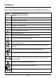
SymbolS Some of the following symbols may be used on this product. Please study them and learn their meaning. Proper interpretation of these symbols will allow you to operate the product better and safer.
SymbolS The following signal words and meanings are intended to explain the levels of risk associated with this product. SYMBOL signal meaning DANGER Indicates an imminently hazardous situation, which, if not avoided, will result in death or serious injury. WARNING Indicates a potentially hazardous situation, which, if not avoided, could result in death or serious injury.
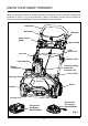
KNOW YOUR snow thrower Read this operator's manual and safety rules before operating your snow thrower. Compare the illustration in Figure 1 to your snow thrower in order to familiarize yourself with the location of various controls and adjustments. Save this manual for future reference.
ASSEMBLY INSTRUCTIONS UNPACKING • Carefully remove the product and any accessories from the box. Make sure that all items listed in the packing list are included. • Inspect the product carefully to make sure no breakage or damage occurred during shipping. • Do not discard the packing material until you have carefully inspected and satisfactorily operated the product. • If any parts are damaged or missing, please call 1-888-909-6757 for assistance.
ASSEMBLY INSTRUCTIONS WA R N I N G Do not allow familiarity with this product to make you careless. Remember that a careless fraction of a second is sufficient to inflict serious injury. WA R N I N G Do not use any attachments or accessories not recommended by the manufacturer of this product. The use of attachments or accessories not recommended can result in serious personal injury. Assembling the Handle (See Figure 2) • Align the holes (4) on the middle handle (2) and the lower handle (3).
ASSEMBLY INSTRUCTIONS Assembling the Discharge Chute (See Figure 3) Push the chute deflector (1) until the latching tabs (2) on either side click into the slots (3) and the posts (4) on either side click into the keyed holes (5). 1 3 5 2 3 5 2 4 4 Fig.
ASSEMBLY INSTRUCTIONS installing the chute control rod (See Figure 4) • Position the discharge chute (1) so that it faces forward. NOTE: Align the arrow (2) on the discharge chute with the arrow on the housing. (Fig. 4.1) • Align the holes (3) on the upper chute control rod (4) with the holes on the lower chute control rod (5). Insert the hitch pin (6). Insert the end of the chute control rod (7) through the keyed hole (8) in the bracket that is attached to the top of the middle handle. (Fig.4.
ASSEMBLY INSTRUCTIONS • Rotate the handle on the chute control rod to ensure that it moves in the same direction as the chute. (Fig.4.4) 9 10 Fig. 4.3 Fig. 4.
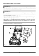
ASSEMBLY INSTRUCTIONS TO INSTALL BATTERY PACK (See Figure 5) • Open the battery compartment cover (1). • Slide the battery (2) down to lock it into position. The battery is fully inserted into the snow thrower when you hear an audible “click”. • Close the battery compartment cover (1). 1 3 2 Fig. 5 TO REMOVE BATTERY PACK (See Figure 5) • Release your grip on the ON/OFF switch bar lever to stop the snow thrower. • Press and hold the battery latch button (3) at the bottom of the battery pack.
OPERATING INSTRUCTIONS POWERING ON AND OFF (See Figure 6) • To power on, first press the safety switch button (1). • While pressing the safety switch button with one hand, use your other hand to simultaneouly pull the bail switch (2) toward you. Once the machine powers on, release the safety switch button and proceed with operation. The snow thrower can only be started by pressing the safety switch button first, followed by squeezing the bail switch; reverse operation will not start the machine.
OPERATING INSTRUCTIONS UTILIZING THE LED LIGHTS (See Figure 7) • To utilize the LED lights (1) for night time snow removal, activate the LED light switch (2). NOTE: After you have finished using your snow thrower, remember to turn off the light switch. 2 1 Fig.
OPERATING INSTRUCTIONS Adjusting the discharge chute and chute deflector (See Figure 8) • To adjust the discharge chute, rotate the handle (1) on the chute control rod in the direction that you wish to direct the snow stream. • To adjust the chute deflector (and therefore the height of the snow stream), squeeze the trigger (2) and raise or lower the chute deflector. 2 1 Fig.
OPERATING INSTRUCTIONS Operating tips WA R N I N G If the Snow Thrower hits a foreign object while it is in use, the object could be thrown in the direction of the operator or a bystander. Thrown objects could cause serious personal injury. Keep the area to be cleared free of all foreign objects that may be picked up and thrown by the impeller. • Keep the area of operation free of foreign objects that can become thrown by the impeller.
MAINTENANCE Servicing Servicing should be performed by a qualified technician. Replacement parts for this Snow Thrower must be identical to the parts that they replace. If repairs are necessary, contact the Toll-Free Helpline, at 1-888-909-6757. Note: Identify the left and right sides of the Snow Thrower when standing in the normal operating position.
MAINTENANCE Replacing the Scraper (See Figure 9) The scraper is located at the bottom of the impeller housing. • Ensure that the battery is not installed in the tool. • Remove the screw (1) from each side plate that holds the scraper and 3 screws (2) from under the machine that secure the scraper to the machine. • Remove and discard the old scraper. • Install the new scraper, and fasten it securely with the 5 screws that you previously removed. 1 1 2 20 Fig.
MAINTENANCE Replacing the DRIVE Belt (See Figures 10) • Ensure that the battery is not installed in the tool. • Remove the 5 screws (1) that secure the left side plate (2) to the frame of the snow thrower. Remove the side cover. • Remove the old belt (3) from the small pulley (5) and large pulley (4). • Loop one end of the new belt over the small pulley. • Rotate the impeller with the left hand while positioning the belt on the large pulley with the right hand.
MAINTENANCE Replacing the impeller (See Figures 11-13) • Remove the 5 screws (1) that secure the right side cover (2) to the frame of the snow thrower. • Remove the nut (3). • Remove the 5 screws (4) that secure the left side cover (5) to the frame of the snow thrower. • Remove the belt (6). • Using a socket wrench, remove the the large pulley (7). • Remove the 5 screws (8) that secure the left side plate (9) and remove the left side plate. • Pull the axle (10) and remove the old impeller (11).
troubleshooting PROBLEM POSSIBLE CAUSE SOLUTION Then handle is not in position. The bolts are not properly seated. Make sure the bolts are correctly installed through the handle bars. Check to see if the hand knobs are tight. Refer to Assembling the Handle section in this manual. The snow thrower doesn't start. The battery is not charged. Charge the battery by following the procedures in the battery and charger manual. The switch is defective.
LIMITED four-YEAR WARRANTY GREENWORKS™ hereby warranties this product, to the original purchaser with proof of purchase, for a period of four (4) years against defects in materials, parts or workmanship. GREENWORKS™, at its own discretion will repair or replace any and all parts found to be defective, through normal use, free of charge to the customer.
EXPLODED VIEW / parts list Item No. 1 2 3 4 5 6 7 8 9 10 11 12 13 14 15 16 17 18 19 20 21 22 23 24 25 26 27 28 29 Part No.
EXPLODED VIEW / parts list Item No. 6 6-1 6-2 6-3 6-4 6-5 6-6 6-7 6-8 6-9 6-10 6-11 6-12 6-13 6-14 6-15 6-16 6-17 6-18 6-19 6-20 6-21 6-22 Part No.
EXPLODED VIEW / parts list Item No. 7 7-1 7-2 7-3 7-4 7-5 7-6 Part No.
EXPLODED VIEW / parts list Item No. 28 28-1 28-2 28-3 28-4 28-5 28-6 28-7 28-8 28-9 28-10 28-11 28-12 28-13 28-14 28-15 28-16 28-17 28-18 28-19 Part No.
TOLL-FREE HELPLINE: 1-888-90WORKS (888.909.