MODEL G0457 14" INDUSTRIAL BANDSAW OWNER'S MANUAL (For models manufactured since 05/11) COPYRIGHT © AUGUST, 2005 BY GRIZZLY INDUSTRIAL, INC. REVISED JUNE, 2018 (BLHE) WARNING: NO PORTION OF THIS MANUAL MAY BE REPRODUCED IN ANY SHAPE OR FORM WITHOUT THE WRITTEN APPROVAL OF GRIZZLY INDUSTRIAL, INC.
This manual provides critical safety instructions on the proper setup, operation, maintenance, and service of this machine/tool. Save this document, refer to it often, and use it to instruct other operators. Failure to read, understand and follow the instructions in this manual may result in fire or serious personal injury—including amputation, electrocution, or death. The owner of this machine/tool is solely responsible for its safe use.
Table of Contents INTRODUCTION................................................ 2 Contact Info.................................................... 2 Manual Accuracy............................................ 2 Identification.................................................... 3 Machine Data Sheet....................................... 4 SECTION 1: SAFETY........................................ 6 Safety Instructions for Machinery................... 6 Additional Safety for Bandsaws......................
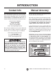
INTRODUCTION Contact Info Manual Accuracy We stand behind our machines! If you have questions or need help, contact us with the information below. Before contacting, make sure you get the serial number and manufacture date from the machine ID label. This will help us help you faster. We are proud to provide a high-quality owner’s manual with your new machine! Grizzly Technical Support 1815 W. Battlefield Springfield, MO 65807 Phone: (570) 546-9663 Email: techsupport@grizzly.
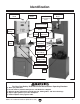
Identification Blade Tension Knob Top Wheel Cover Blade Tension Quick Release Lever Blade Tension Scale Blade Tracking Adjustment Knob ON/OFF Switch Guide Adjustment Knob Blade Guard Guide Post Lock Knob Blade Guide Assembly Resaw Fence Miter Gauge Assembly Resaw Lock Handle Table Trunnion Hand Knob Dust Port Table Tilt Scale (Under Table) Fence Lock Lever Bottom Wheel Cover Motor a) b) c) d) e) For Your Own Safety, Read Instruction Manual Before Operating Bandsaw Wear eye protection.
Machine Data Sheet MACHINE DATA SHEET Customer Service #: (570) 546-9663 · To Order Call: (800) 523-4777 · Fax #: (800) 438-5901 MODEL G0457 14" 2 HP DELUXE BANDSAW Product Dimensions: Weight.............................................................................................................................................................. 251 lbs. Width (side-to-side) x Depth (front-to-back) x Height............................................................... 29-3/4 x 29-1/2 x 73 in.
Main Specifications: Main Specifications Bandsaw Size............................................................................................................................................ 14 in. Max Cutting Width (Left of Blade)........................................................................................................ 13-1/2 in. Max Cutting Width (Left of Blade) w/Fence......................................................................................... 12-1/4 in.
SECTION 1: SAFETY For Your Own Safety, Read Instruction Manual Before Operating This Machine The purpose of safety symbols is to attract your attention to possible hazardous conditions. This manual uses a series of symbols and signal words intended to convey the level of importance of the safety messages. The progression of symbols is described below. Remember that safety messages by themselves do not eliminate danger and are not a substitute for proper accident prevention measures.
WEARING PROPER APPAREL. Do not wear clothing, apparel or jewelry that can become entangled in moving parts. Always tie back or cover long hair. Wear non-slip footwear to reduce risk of slipping and losing control or accidentally contacting cutting tool or moving parts. HAZARDOUS DUST. Dust created by machinery operations may cause cancer, birth defects, or long-term respiratory damage. Be aware of dust hazards associated with each workpiece material.
Additional Safety for Bandsaws Serious cuts, amputation, or death can occur from contact with the moving saw blade during operation or if blade breakage occurs. To reduce this risk, anyone operating this machine MUST completely heed the hazards and warnings below. HAND PLACEMENT. Placing hands or fingers in line with blade during operation may result in serious injury if hands slip or workpiece moves unexpectedly.
SECTION 2: POWER SUPPLY Availability Circuit Information Before installing the machine, consider the availability and proximity of the required power supply circuit. If an existing circuit does not meet the requirements for this machine, a new circuit must be installed. To minimize the risk of electrocution, fire, or equipment damage, installation work and electrical wiring must be done by an electrician or qualified service personnel in accordance with all applicable codes and standards.
Grounding Requirements This machine MUST be grounded. In the event of certain malfunctions or breakdowns, grounding reduces the risk of electric shock by providing a path of least resistance for electric current. For 220V operation: This machine is equipped with a power cord that has an equipment-grounding wire and a grounding plug (see following figure).
Extension Cords We do not recommend using an extension cord with this machine. If you must use an extension cord, only use it if absolutely necessary and only on a temporary basis. Disabling & Locking Switch Extension cords cause voltage drop, which can damage electrical components and shorten motor life. Voltage drop increases as the extension cord size gets longer and the gauge size gets smaller (higher gauge numbers indicate smaller sizes).
SECTION 3: SETUP Needed for Setup This machine presents serious injury hazards to untrained users. Read through this entire manual to become familiar with the controls and operations before starting the machine! Wear safety glasses during the entire setup process! This machine and its components are very heavy. Get lifting help or use power lifting equipment such as a forklift to move heavy items.
Hardware Recognition Chart 5mm G0457 14" Industrial Bandsaw (Mfd.
Inventory A The following is a list of items shipped with your machine. Before beginning setup, lay these items out and inventory them. If any non-proprietary parts are missing (e.g. a nut or a washer), we will gladly replace them; or for the sake of expediency, replacements can be obtained at your local hardware store. Contents (Figures 4–5) Qty A. Bandsaw Unit.............................................. 1 B. Cabinet Stand.............................................. 1 C. Feet 3 ⁄ 8-16 (Stand)..........
The unpainted surfaces are coated with a waxy oil to prevent corrosion during shipment. Remove this protective coating with a solvent cleaner or degreaser. For thorough cleaning, some parts must be removed. For optimum performance, clean all moving parts or sliding contact surfaces. Avoid chlorine-based solvents, such as acetone or brake parts cleaner that may damage painted surfaces. Always follow the manufacturer’s instructions when using any type of cleaning product.
Assembly 4. With the help of an assistant, set the bandsaw unit onto the stand, align the mounting holes, then open the door on the cabinet stand. The machine must be fully assembled before it can be operated. Before beginning the assembly process, refer to Needed for Setup and gather all listed items. To ensure the assembly process goes smoothly, first clean any parts that are covered or coated in heavy-duty rust preventative (if applicable). 5.
7. Thread an M8-1.25 hex nut all the way onto the quick release lever, as shown in Figure 11, then thread the lever into the quick release hub and tighten the hex nut against the hub to lock the lever in place. 9. From the inside of the bandsaw, loosely fasten the motor to the body with the cap screws, lock washers, and flat washers, as shown in Figure 13. Wheel Removed for Clarity Hex Nut Figure 11. Quick release lever installed. 8.
15. Replace the blade, and for now, only put enough tension on it to keep it on the wheels. 16. Re-install the table pin and table insert. 17. Fasten the rear rail to the back of the table with two M6-1 x 16 cap screws, as shown in Figure 15. 19. Thread an M8-1.25 hex nut all the way onto the fence lock lever shown in Figure 17, then thread the lever handle into fence pivot block and tighten the hex nut against the pivot block to secure the handle. Pivot Block Hex Nut Figure 17.
Dust Collection 23. Pull the handle up and place the fence assembly on the fixed rail, as shown in Figure 19. DO NOT operate the Model G0457 without an adequate dust collection system. This saw creates substantial amounts of wood dust while operating. Failure to use a dust collection system can result in short and long-term respiratory illness. Figure 19. Correctly installed fence. 24. Push the handle down to lock the fence assembly in place. 25.
Blade Tracking The blade tracking is primarily affected by the tilt of the upper wheel, also known as "Center Tracking"; and the alignment of both wheels, also known as "Coplanar Tracking." (For Coplanar Tracking, see the Wheel Alignment instructions on Page 49.) Blade Centered on Peak of Crown Blade Centered on Wheel The wheels on the Model G0457 were aligned at the factory, so Center Tracking is the only adjustment that needs to be performed when the saw is new. To center track the blade: 1.
Table Stop Calibration Test Run Once assembly is complete, test run the machine to ensure it is properly connected to power and safety components are functioning correctly. If you find an unusual problem during the test run, immediately stop the machine, disconnect it from power, and fix the problem BEFORE operating the machine again. The Troubleshooting table in the SERVICE section of this manual can help.
Table Tilt Calibration Table Alignment The pointer on the table tilt scale must be calibrated in order for the scale reading to be accurate. To ensure cutting accuracy when the table is first installed, the table should be aligned so that the miter slot is parallel to the bandsaw blade. This procedure works best with a 3 ⁄4" blade installed. To calibrate the pointer on the table tilt scale: 1. 2.
Fence Alignment Miter Gauge To ensure cutting accuracy when the fence is first installed, the fence should be aligned with the miter slot. The miter gauge needs to be calibrated to the blade when it is first mounted in the miter slot. To align the fence parallel with the miter slot: 1. If the fence is mounted on the left-hand side of the blade, remove it and remount it next to the miter slot. 2. Loosen the four cap screws located on the top face of the fence (Figure 27).
Blade Tensioning A properly tensioned blade is essential for making accurate cuts and is a prerequisite for making many bandsaw adjustments. The blade tension scale shows the approximate tension, but the steps below will allow you to get the optimum tension for the installed blade. NOTICE After blade tension and tracking are set correctly, you MUST properly adjust the upper and lower support bearings and guide-block assemblies into position before cutting.
4. Loosen the assembly lock bolt. 5. Rotate the blade guide assembly side-toside, until the blade is perpendicular to the face of the support bearing as illustrated in Figure 30. Note: For a quick gauge, fold a dollar bill in half twice (four thicknesses of a dollar bill is approximately 0.016") and place it between the support bearing and the blade as shown in Figure 32. Bandsaw Blade Support Bearing Figure 32. Dollar bill folded twice to make an approximate 0.016" gauge. Top View Figure 30.
Blade Guide Adjustments Approximately 0.016" Blade Guide Bearing The blade guides consist of an upper and lower set of ball bearings that provide side-to-side support to help keep the blade straight while cutting. The blade guides are designed to be adjusted in two ways—forward/backward and side-to-side. Blade Gullets To adjust the upper and lower blade guides: 1. Make sure that the blade is tracking properly and that it is correctly tensioned. Figure 34. Lateral adjustment of blade guides. 2.
SECTION 4: OPERATIONS Basic Controls To reduce your risk of serious injury, read this entire manual BEFORE using machine. Use the descriptions and figures below to become familiar with the basic controls of your machine. Blade Tension Knob: Adjusts the tension on the blade. Damage to your eyes and lungs could result from using this machine without proper protective gear. Always wear safety glasses and a respirator when operating this machine.
Overview ON/OFF Switch: Starts and stops the blade motor. Miter Gauge Lock Handle: Locks the miter gauge at the current setting. Fence Lock Lever: Locks the fence at its current position. Miter Gauge Lock Handle The bandsaw is one of the most versatile wood cutting tools in the shop. It is capable of performing many different cutting functions, including: Straight Cuts • • • • • • Miters Angles Compound Angles Resawing Ripping Crosscutting ON/OFF Switch Irregular Cuts Fence Lock Lever Figure 36.
Workpiece Inspection Some wood workpieces are not safe to cut or may require modification before they are safe to cut. Before making cuts, get in the habit of inspecting all workpieces for the following: • Material Type: This machine is intended for cutting natural and man-made wood products, laminate covered wood products, and some plastics. Cutting drywall or cementitious backer board creates extremely fine dust and may reduce the life of the bearings.
Guide Post Ripping The guide post, shown in Figure 37, connects the upper blade guide assembly to the bandsaw. The guide post allows the blade guide assembly to move up or down via a rack and pinion. In order to cut accurately, the blade guide assembly must be no more than 1" from the top of the workpiece at all times—this positioning provides the greatest support to the blade. Ripping is the process of cutting with the grain of the wood stock.
Crosscutting Resawing Crosscutting is the process of cutting across the grain of wood. For plywood and other processed wood, crosscutting simply means cutting across the width of the material. Resawing (Figure 40) is the process of cutting a board into two or more thinner boards. The maximum board width that can be resawn is limited by the maximum cutting height of the bandsaw. Maximum cutting height for this bandsaw is 10". To crosscut with the Model G0457: 1.
To resaw a workpiece: 1. 2. Verify that the bandsaw is set up properly and that the table is perpendicular to the blade. Use the widest blade your bandsaw will accept. Note: The blade must also be sharp and clean. 3. Use a fence to guide the workpiece. 4. Set your fence to the desired width of cut and lock it in place. 5. Support the ends of the board if necessary. 6. Turn the bandsaw ON. 7.
Stacked Cuts One of the benefits of a bandsaw is its ability to cut multiple copies of a particular shape by stacking a number of workpieces together. Before making stacked cuts, ensure that both the table and the blade are properly adjusted to 90°. Otherwise, any error will be compounded with each piece cut from the top to the bottom of the stack. 5. Cut the stack of pieces as though you were cutting a single piece.
Blade Information • Selecting the right blade requires a knowledge of the various blade characteristics mentioned below, the type of material you plan to cut, and the type of cut you are going to perform. Blade Length Measured by the circumference, blade lengths are usually unique to the brand of your bandsaw and the distance between wheels. The Model G0457 is designed for blades that are 106" long. Refer to the current Grizzly catalog for prices and ordering information.
• Hook: The teeth on this style have a positive angle (downward) which makes them dig into the material, and the gullets are usually rounded for easier waste removal. These blades are excellent for the tough demands of resawing and ripping thick material. Tooth Pitch Usually measured as TPI (teeth per inch), tooth pitch determines the size of the teeth. More teeth per inch (fine pitch) will cut slower, but smoother; while fewer teeth per inch (coarse pitch) will cut rougher, but faster.
Blade Changes Always disconnect power to the machine when changing blades. Failure to do this may result in serious personal injury. To replace the blade: 1. Slide the blade through the table slot, ensuring that the teeth are pointing down toward the table. Note: If the teeth will not point downward in any orientation, the blade is inside-out. Put on heavy gloves, remove the blade, and twist it right side-out. 2. Slip the blade through the guides, and mount it on the upper and lower wheels (Figure 44).
ACCESSORIES SECTION 5: ACCESSORIES Basic Eye Protection Installing unapproved accessories may cause machine to malfunction, resulting in serious personal injury or machine damage. To reduce this risk, only install accessories recommended for this machine by Grizzly. T20501—Face Shield Crown Protector 4" T20502—Face Shield Crown Protector 7" T20503—Face Shield Window T20451—“Kirova” Clear Safety Glasses T20452—“Kirova” Anti-Reflective S.
H2499—Small Half-Mask Respirator H3631—Medium Half-Mask Respirator H3632—Large Half-Mask Respirator H3635—Cartridge Filter Pair P100 Wood dust has been linked to nasal cancer and severe respiratory illnesses. If you work arounddust everyday, a half-mask respirator can be a lifesaver. Also compatible with safety glasses! H5408—Blade Tensioning Gauge The Blade Tensioning Gauge ensures long blade life, reduced blade breakage, and straight cutting by indicating correct tension.
T26403—The Missing Shop Manual: Bandsaw Dedicated to providing integral information about woodworking tools and techniques that other manuals overlook, the books in this series contain safety facts, explanations about basic project set up, and tips for maximizing tool performance. In Bandsaw, you will find out how to best utilize this essential workshop tool, and how to get the most for your money by getting the most from your equipment.
SECTION 6: MAINTENANCE Always disconnect power to the machine before performing maintenance. Failure to do this may result in serious personal injury. Schedule For optimum performance from this machine, this maintenance schedule must be strictly followed. Ongoing To maintain a low risk of injury and proper machine operation, if you ever observe any of the items below, shut down the machine immediately and fix the problem before continuing operations: • • • • Loose mounting bolts.
Guide Post Blade Tension Leadscrew 1. DISCONNECT BANDSAW FROM POWER! 1. DISCONNECT BANDSAW FROM POWER! 2. Open the upper wheel cover, then lower the guide post so the upper guide bearings almost touch the table. 2. 3. Wipe the old grease off the rack (the long plate with teeth). The old grease will be contaminated with sawdust, so you want to remove as much of it as possible (Figure 55). Open the upper wheel cover, then wipe as much of the old grease off the blade tension leadscrew as possible.
Redressing Rubber Tires Table Trunnions 1. DISCONNECT BANDSAW FROM POWER! 2. Wipe the old grease off the bearing surfaces of the table trunnions. Start with the outward side of the table trunnions (Figure 57) when the table is at 0°, then tilt the table to 45° and wipe off the inward side. The old grease will be contaminated with sawdust, so you want to remove as much of it as you can.
SECTION 7: SERVICE Review the troubleshooting procedures in this section if a problem develops with your machine. If you need replacement parts or additional help with a procedure, call our Technical Support. Note: Please gather the serial number and manufacture date of your machine before calling. Troubleshooting Motor & Electrical Symptom Possible Cause Possible Solution Machine does not start or a breaker trips. 1. Plug/receptacle is at fault or wired incorrectly. 2.
Symptom Possible Cause Possible Solution 1. Inspect/replace stripped or damaged bolts/nuts, and re-tighten with thread locking fluid. 2. Inspect/replace belt (Page 46). 3. Replace dented fan cover and loose/damaged fan. 4. Realign/replace shaft, pulley, set screw, and key as required. 5. Machine is incorrectly mounted or sits unevenly 5. Adjust the feet on the bottom of the stand; relocate machine. on floor. 6. Test by rotating shaft — rotational grinding/loose shaft 6. Motor bearings are at fault.
Checking V-Belt Motor Adjustment Screw To ensure optimum power transmission from the motor to the blade, the V-belt must be in good condition and operate under proper tension. The belt should be checked for cracks, fraying, and wear. Belt tension should be checked at least every 3 months—more often if the bandsaw is used daily. Motor Hinge Screw To check the V-belt: 1. DISCONNECT BANDSAW FROM POWER! 2. Open the lower wheel cover. 3. Push the center of the V-belt. Note the amount of deflection.
Replacing V-Belt Tools Needed: QTY Hex Wrench 6mm................................................1 Wrench 13mm.....................................................1 5. Move the body of the motor so that the motor adjustment screw slides to the right-hand side (facing bandsaw front) of the adjustment slot and pull the V-belt off of the motor pulley. 6. Slip the old V-belt off of the wheel pulley and install the new V-belt in its place. 7.
Shimming Table Blade Lead To ensure accuracy when cutting stacked workpieces, the table should be 90˚ to the back of the blade as shown in Figure 61. If the table is not perpendicular to the back of the blade, the table needs to be shimmed. Bandsaw blades sometimes wander off the cut line when sawing, as shown in Figure 62. This is called blade lead. Blade lead is commonly caused by too fast of a feed rate, a dull or abused blade, or improper tension.
3. Clamp the board to the bandsaw table without moving it. Now slide the fence over to the board so it barely touches one end of the board. 4. Loosen the four cap screws on top of the fence. 5. Skew the fence so it is parallel to the edge of the scrap piece. You may need to re-adjust the fence locking mechanisms to gain maximum adjustment. 6. While maintaining the skew, tighten the cap screws. NOTICE Lead adjustments will change when new blades are mounted on the saw. -48- Shifting Table 1.
Wheel Alignment 31/2" Components and Hardware Needed: Qty 1 45 /2" Long 2x4................................................... 1 Tools Needed: Wrench 13mm.................................................... 1 Tape Measure..................................................... 1 Coplanarity Gauge (see Figure 63)................... 1 14" Wheel alignment is one of the most critical factors for optimal performance from your bandsaw.
6. 7. 8. Adjust the tracking knob to get both wheels parallel. If the wheels won’t go parallel to each other, then move the lower wheel at the adjustment hub so they line up. If the wheels will go parallel but not coplanar, then move the lower wheel at the adjustment hub (Figure 65) as necessary. Figure 66 shows the positions of the wheels when coplanar. When your wheels are coplanar, readjust the guide blocks and rear support bearings, and replace the wheel covers.
machine SECTION 8: WIRING These pages are current at the time of printing. However, in the spirit of improvement, we may make changes to the electrical systems of future machines. Compare the manufacture date of your machine to the one stated in this manual, and study this section carefully. If there are differences between your machine and what is shown in this section, call Technical Support at (570) 546-9663 for assistance BEFORE making any changes to the wiring on your machine.
Wiring Diagram Ground TRATS Hot Neutral 220 VAC Hot Hot 5-20 Plug (As Recommended) Wt Gn 220V G 110V Bl PUSH BUTTON SWITCH (viewed from behind) 6-15 Plug (As Recommended) POTS Wt Gn Bl Ground Bl Wt Gn Bl Wt Gn Rewired to 110V 220V (Prewired) 110V 1 Run Capacitor 40MFD 250VAC 3 2 1 4 4 3 2 Start Capacitor 300MFD 250VAC Ground Ground Bl Gn Wt Bl Gn Wt Rewired to 110V Figure 67. 220V motor wiring. -52- READ ELECTRICAL SAFETY ON PAGE 51! Figure 68.
SECTION 9: PARTS Main 12 2 26 11 8 10 7 6 9 21 5 4 55 94 92 91 90 76 88 97 28 29 161 162 23 22 25 144 31 32 34 38 37 42 204 112 65 116 117 118 52 119 120A 123 124 53 57 37 41 56 58 43 59 63 60 61 64 62 67 68 69 70 71 72 75 76 66 73 87 160 125 77 78 74 86 44 113 114 96V2-1 96V2-3 96V2-10 96V2-2 96V2-11 78 115 202 83 82 81 80 79 96V2-5 135 96V2-6 51 54 40 39 203 96V2 96V2-4 50 35 36 54 24 142 143 30 100 101 102 66 151 104 158 159 150 111 164
Main Parts List REF PART # DESCRIPTION REF PART # DESCRIPTION 1 2 3 4 5 6 7 8 9 10 11 12 21 22 23 24 25 26 27 28 29 30 31 32 33 34 35 36 37 38 39 40 41 42 43 44 50 51 52 53 54 55 56 57 58 59 60 61 62 63 64 65 66 67 BODY UPPER WHEEL DOOR LOWER WHEEL DOOR CAP SCREW M6-1 X 10 LOCK WASHER 6MM CAP SCREW M5-.8 X 12 BIAS SHAFT BIAS SHAFT CLAMP SEAT TENSION ADJUSTMENT HUB CAP SCREW M8-1.25 X 20 HEX NUT M8-1.25 TENSION HANDLE CAP SCREW M6-1 X 10 LOCK WASHER 8MM CAP SCREW M8-1.25 X 20 LOCK KNOB M8-1.
Main Parts List (Continued) REF PART # DESCRIPTION REF PART # DESCRIPTION 119 120A 121 122 123 124 125 126 127 128 129 130 131A 132 133 134 135 136 137 138 139 LOCK WASHER 8MM TRUNNION BRACKET CAST IRON HEX BOLT M8-1.25 X 80 HEX NUT M8-1.25 POINTER PHLP HD SCR M5-.8 X 6 LOCK KNOB M10-1.5 TABLE INSERT TABLE PIN TABLE HEX BOLT M10-1.5 X 50 TRUNNION CLAMP SHOE 1PC TRUNNION CAST IRON SCALE FLANGE BOLT M6-1 X 12 BLADE 106 X 3/8 X 0.35" 6TPI FLANGE SCREW M5-.8 X 8 PHLP HD SCR M4-.7 X 10 PHLP HD SCR M5-.
Components 149-28 149-20 149 149-30 148 149-18 149-11 149-16 149-2 149-12 149-4 149-13 149-15 149-22 149-10 149-8 149-6 149-24 149-5 149-7 149-26 149-9 149-3 149-29 149-23 149-27 149-14 149-25 149-19 149-21 149-1 149-17 149-20 REF PART # DESCRIPTION REF PART # DESCRIPTION 148 149 149-1 149-2 149-3 149-4 149-5 149-6 149-7 149-8 149-9 149-10 149-11 149-12 149-13 149-14 P0457148 P0457149 P0457149-1 P0457149-2 P0457149-3 P0457149-4 P0457149-5 P0457149-6 P0457149-7 P0457149-8 P0457149-9
Stand 301 302 303 305 304 306 307 308 309 REF PART # DESCRIPTION REF PART # DESCRIPTION 301 302 303 304 305 CARRIAGE BOLT M8-1.25 X 20 STAND FLANGE NUT M8-1.25 FOAM TAPE DOOR 306 307 308 309 LATCH ASSEMBLY FLAT WASHER 10MM HEX NUT 3/8-16 FOOT 3/8-16 X 1-3/4 P0457301 P0457302 P0457303 P0457304 P0457305 G0457 14" Industrial Bandsaw (Mfd.
Labels 410 401 409 407 411 404 406 408 405 402 412 403 407 405 Rear of Machine REF PART # DESCRIPTION REF PART # DESCRIPTION 401 402 403 404 405 406 MACHINE ID LABEL READ MANUAL LABEL UNPLUG BANDSAW LABEL SAFETY GLASSES LABEL DO NOT OPEN LABEL BLADE TENSION NOTICE LABEL 407 408 409 410 411 412 HANDS NEAR BLADE LABEL ELECTRICITY LABEL GRIZZLY NAMEPLATE MODEL NUMBER LABEL BLADE GUARD ADJ LABEL BLADE TENSION SCALE/LABEL P0457401 P0457402 P0457403 P0457404 P0457405 P0457406 P0457407 P0457408
WARRANTY CARD Name _____________________________________________________________________________ Street _____________________________________________________________________________ City _______________________ State _________________________ Zip _____________________ Phone # ____________________ Email _________________________________________________ Model # ____________________ Order # _______________________ Serial # __________________ The following information is given on a voluntary basis.
FOLD ALONG DOTTED LINE Place Stamp Here GRIZZLY INDUSTRIAL, INC. P.O.
WARRANTY & RETURNS Grizzly Industrial, Inc. warrants every product it sells for a period of 1 year to the original purchaser from the date of purchase. This warranty does not apply to defects due directly or indirectly to misuse, abuse, negligence, accidents, repairs or alterations or lack of maintenance.