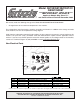
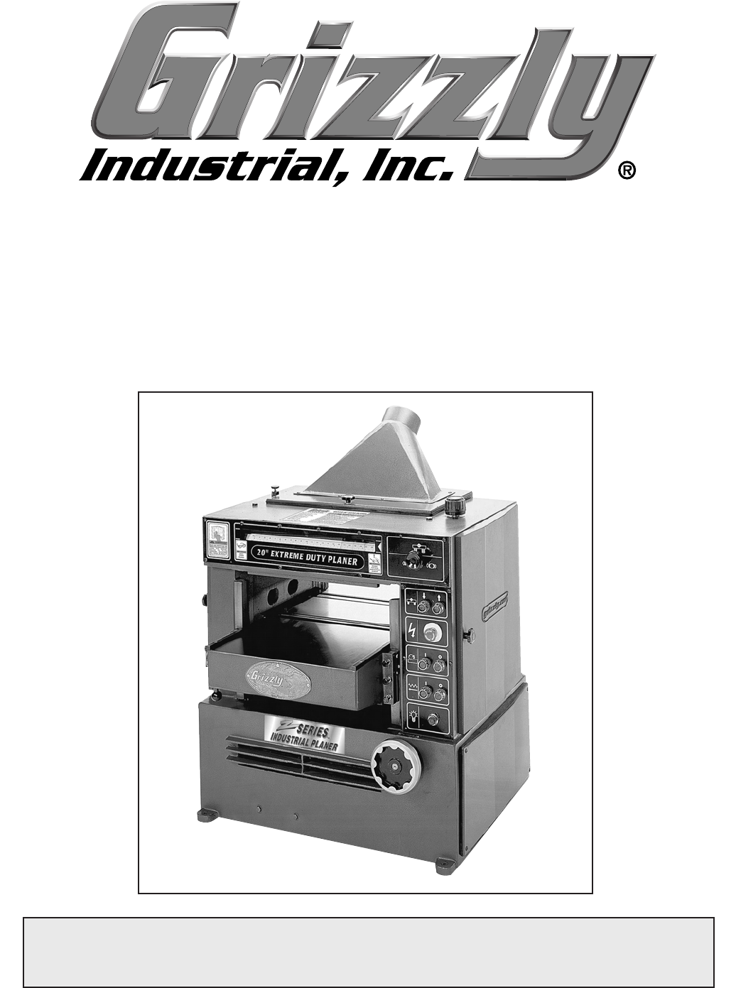
EXTREME-DUTY PLANERS MODELS G9740/G9740Z/G9741/G9961/G9967/G9967Z INSTRUCTION MANUAL Model G9740 Shown COPYRIGHT © SEPTEMBER, 2003 BY GRIZZLY INDUSTRIAL, INC. REVISED NOVERMBER, 2003. WARNING: NO PORTION OF THIS MANUAL MAY BE REPRODUCED IN ANY SHAPE OR FORM WITHOUT THE WRITTEN APPROVAL OF GRIZZLY INDUSTRIAL, INC.
WARNING Some dust created by power sanding, sawing, grinding, drilling, and other construction activities contains chemicals known to the State of California to cause cancer, birth defects or other reproductive harm. Some examples of these chemicals are: • Lead from lead-based paints. • Crystalline silica from bricks, cement, and other masonry products. • Arsenic and chromium from chemically treated lumber. Your risk from these exposures varies, depending on how often you do this type of work.
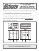
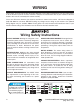
Models G9740, G9740Z, G9741, G9961 ***IMPORTANT UPDATE*** Applies to Models Mfg. Since June, 2012 and Owner's Manual Revised November, 2003 The following changes were recently made to these machines, making some parts of the owner's manual no longer applicable: • Cutterhead motor wiring and main wiring changed to the Star-Delta start configuration.
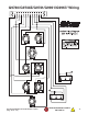
Updated Main Wiring Diagram -2- G9740-40Z, G9741, G9961 Update (Mfg.
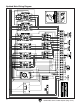
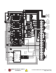
Model G9740/G9740Z/G9741/ G9961/G9967 119 ***IMPORTANT UPDATE*** 118 Applies to Models Mfg. Since 1/11 and Owner's Manual Revised November, 2003 121 We recently made the following change to the Model G9740/G9740Z/G9741/G9961/G9967: 104 • 120 Changed some of the electrical components in the machine. This change does not affect how the machine assembles or functions. In addition to the change we made to the machine, we have also updated the 112 wiring diagram.
WIRING machine These pages are current at the time of printing. However, in the spirit of improvement, we may make changes to the electrical systems of future machines. Compare the manufacture date of your machine to the one stated in this manual, and study this section carefully. If there are differences between your machine and what is shown in this section, call Technical Support at (570) 546-9663 for assistance BEFORE making any changes to the wiring on your machine.
G9740/G9740Z/G9741/G9961/G9967/ Wiring G9740/G9740Z/G9741/G9961/G9967 Update (Mfg.
-4- READ ELECTRICAL SAFETY ON PAGE 2! G9740/G9740Z/G9741/G9961/G9967 Update (Mfg.
Table Of Contents SECTION 1: SAFETY ....................................................................................................................... 2 Safety Instructions For Power Tools .......................................................................................... 2 Additional Safety Instructions For Planers ................................................................................. 4 SECTION 2: GENERAL INFORMATION ...................................................................
SECTION 1: SAFETY For Your Own Safety Read Instruction Manual Before Operating This Equipment The purpose of safety symbols is to attract your attention to possible hazardous conditions. This manual uses a series of symbols and signal words which are intended to convey the level of importance of the safety messages. The progression of symbols is described below. Remember that safety messages by themselves do not eliminate danger and are not a substitute for proper accident prevention measures.
Safety Instructions For Power Tools 9. USE PROPER EXTENSION CORD. Make sure your extension cord is in good condition. Conductor size should be in accordance with the chart below. The amperage rating should be listed on the motor or tool nameplate. An undersized cord will cause a drop in line voltage resulting in loss of power and overheating. Your extension cord must also contain a ground wire and plug pin. Always repair or replace extension cords if they become damaged.
Additional Safety Instructions For Planers 1. READ THIS ENTIRE MANUAL BEFORE TURNING THE PLANER ON. 2. ENSURE THAT THE MACHINE IS ON FLAT, STABLE GROUND BEFORE USE. Any “wobbles” must be corrected by shimming or blocking before operation. 3. NEVER PLANE MATERIAL OTHER THAN WOOD WITH THIS MACHINE. 4. NEVER POSITION FINGERS OR THUMBS NEAR THE INFEED ROLLER. 5. ENSURE THAT THE PLANER IS PROPERLY ADJUSTED AND THAT THERE ARE NO LOOSE PARTS BEFORE OPERATING. 6.
SECTION 2: GENERAL INFORMATION Read the manual before assembly and operation. Become familiar with the machine and its operation before beginning any work. Serious personal injury may result if safety or operational information is not understood or followed. Grizzly Industrial, Inc. is proud to offer the Extreme Duty Planers. These planers are part of Grizzly’s growing family of fine woodworking machinery.
SECTION 3: CIRCUIT REQUIREMENTS G9967/G9967Z G9740/G9740Z The Model G9967/G9967Z Planer is prewired with a 5 HP 220V single-phase motor. Please use the following specs when preparing your shop for the machine, and always have the wiring inspected by a licensed electrician before operating your machine. The Model G9740/G9740Z is prewired with a 71⁄2 HP 220V 3-phase motor, which may be rewired to 440V.
G9741/G9961 Grounding The Model G9740/G9740Z Planer is prewired with a 10 HP 3-phase motor, which may be rewired to 440V. Please use the following specs preparing your shop for the machine, and always have the wiring inspected by licensed electrician before operating your machine. In the event of an electrical short, grounding reduces the risk of electric shock by providing a path of least resistance to disperse electric current.
Rewire to 440V The Model G9740/G9740Z/G9741/G9961 can be rewired from 220V to 440V. Before rewiring, purchase the Grizzly 440V conversion kit (#P97400120-11). Please Note—The Model G9967/G9967Z cannot be rewired to 440V. The 440V wiring conversion procedure requires rewiring the transformer, installing new overload relays for the feed and elevation motors, setting all the overload relay dials to the correct position, and rewiring the motors. To rewire the planer: 1.
SECTION 4: MACHINE FEATURES About this Section Familiarize yourself with the planer controls before turning the machine on. Figures 18 and 19 point out these controls. Cutterhead Pressure Bar Chip Breaker Front Feed Roller Rear Feed Roller Anti-Kickback Claw Bed Rollers Table Height Power Cutterhead Motor Table Bed Roller Height Lever Figure 6. Planer components. Feed Motor Power Indicator Light Figure 18. Control panel.
SECTION 5: SET UP About this Section Unpacking The purpose of this section is to guide you through the required steps to get your machine out of its crate and into operating condition. Your machine was carefully packed when it left our warehouse. If you discover the machine is damaged after you have signed for delivery, please immediately call our Customer Service at (570) 546-9663 for advice. This machine presents serious injury hazards to untrained users.
Piece Inventory After all the parts have been removed from the carton, you should have: G9740/G9741/G9967 (4-Knife Cutterheads) Part • Planer Unit • Dust Hood • Combo Wrench 11x13 • Combo Wrench 12x14 • Combo Wrench 17x19 • Hex Wrench 5mm • Knife Setting Jig Extreme Duty Planers Qty 1 1 1 1 1 1 1 G9740Z/G9961/G9967Z (Spiral Cutterheads) Part Qty • Planer Unit 1 • Dust Hood 1 1 • T-20 Torx® Driver • Misc. Bag of T-20 Driver Bits 1 • Misc.
Hardware Recognition Chart -12- Extreme Duty Planers
Clean Up The unpainted surfaces are coated with a waxy oil to protect them from corrosion during shipment. Remove this protective coating with a solvent cleaner or citrus-based degreaser such as Grizzly’s G7895 Degreaser. To clean thoroughly, some parts may need to be removed. For optimum performance from your machine, make sure you clean all moving parts or sliding contact surfaces that are coated. Avoid chlorine-based solvents as they may damage painted surfaces should they come in contact.
SECTION 6: ASSEMBLY Beginning Assembly Dust Hood Most of your Extreme Duty Planer has been assembled at the factory, but some parts must be assembled or installed after delivery. We have organized the assembly process into steps. Please follow along in the order presented in this section. A dust hood with a 5" dust port comes with the planer for dust collection purposes. Install the dust hood with M6-1.0 x 10 screws. The dust hood should look like Figure 4 when installed.
Table Rollers 2. The scale at the base of the adjustment lever is numbered “0”, “1” and “2”. These numbers represent how many millimeters the top of the rollers are above the surface of the table. The height of the table rollers will vary, depending on the type of material you intend to plane. When planing rough stock, you will need to set the rollers high to keep the lumber from dragging along the table. Milled lumber should be planed with the rollers set lower. Since 1mm = .
Test Run Read the entire manual before making any cuts with your planer. Serious personal injury may result if safety or operational information is not understood or followed. Once assembly is complete and adjustments are done to your satisfaction, you are ready to start the machine. Turn on the power supply at the main panel. Press the START button. Make sure your finger is poised on the STOP button, just in case there is a problem.
SECTION 7: OPERATIONS Operational Tips Keep loose clothing out of the way of machinery and keep hair pulled back. Disconnect power to the machine when performing any adjustments or maintenance. Failure to do this may result in serious personal injury. Wear safety glasses during all operations on the planer. Failure to comply may result in serious personal injury. Always wear a dust mask when operating the planer.
Wood Characteristics The species of wood, as well as condition, will affect planing ability—the harder the wood, the more difficult it will be to plane. We have included a list of wood characteristics you may encounter when planing, The following descriptions of defects will give you some possible answers to problems that may arise. Chipped Grain (Tear Out) — Usually a result of cutting against the grain, or planing wood with knots or excessive amount of cross grain.
SECTION 8: MAINTENANCE Disconnect power to the machine when performing any adjustments or maintenance. Failure to do this may result in serious personal injury. General Periodic maintenance on your 20" Extreme Duty Planer Planer ensures its optimum performance. Make a habit of inspecting your planer each time you use it. Table The table and other non-painted surfaces on the Extreme Duty Planer should be protected against rust and pitting.
2. V-Belt Transmission Box — Lubricate after every 12 hours of continuous use. See Figure 21 for location. Avoid getting grease or oil on the V-belts or pulleys. Check the V-belts, as part of a monthly inspection for proper tension and belt condition. Cracking and glazing could result in belt failure. Replace the belt if such conditions appear. To loosen/tighten belt tension: 1. Thread in the motor mount adjustment bolts (Figure 23) to loosen the V-belt.
Maintenance Log Date Approximate Hours Of Use Extreme Duty Planers Maintenance Performed -21-
SECTION 9: SERVICE ADJUSTMENTS Adjustment Controls Always disconnect power to the machine before performing service adjustments. Failure to do this may result in serious personal injury. Figures 5 and 6 point out the primary controls and components that will be used during the adjustment process. Take a few minutes to familiarize yourself with these. Micro-Adjust Height Knob Cutterhead Lock Planer knives are dangerously sharp! Use extreme caution when working near cutting surfaces.
Cutterhead Knives The Model G9740/G9741/G9967 features a 4knife cutterhead. The knives are factory set to .071". Unless you are having problems related to the knives or are removing them for sharpening/replacement, assume that your knives are adjusted correctly. To be safe, always test the planer with a scrap piece of wood before using expensive stock. 3. Remove the hex nuts and springs from the tension studs shown in Figure 8. This will allow the pressure bar to rotate up and over the cutterhead. 4.
3. Wear heavy leather gloves or place a rag over the exposed knife to protect your hands if the wrench slips while loosening the gib bolts. Loosen all the gib bolts on one knife. 4. Insert a 4mm hex wrench into the jack screws (accessible from holes in the cutterhead) as shown in Figure 9. Turn these screws to lower the knife enough to clear the jig when it is placed on the cutterhead body. 10. Replace all of the removed planer parts and adjust the pressure bar (pages 17-18) before operating the planer.
5. Note—Torx® screws that are difficult to remove with the air wrench can be removed with the supplied T-handle. Carefully insert a Torx® bit into the hole on the side of the “cheater bar.” This should allow you enough leverage to loosen the Torx® screws. Reference Dot Figure 10. Always rotate carbide cutters in the same direction to keep track of the dull or damaged edges. To install/adjust the carbide cutters: 1. Disconnect the planer from the power source! 2.
Table 3. The table movement is critical to the operation of the Extreme Duty Planers. For the feed rollers to work correctly, the table must be parallel with the cutterhead. We strongly suggest using a Rotacator® for making adjustments to your planer. This tool is well worth the money, because it provides accuracy within .001". Check with the current Grizzly catalog for details. Set the Rotacator® dial to .000". Place the Rotacator® under the cutterhead on one end.
To check the table with the block of wood: To adjust the table with the Rotacator®: 1. Make sure the planer is disconnected from the power source! 1. Make sure the planer is disconnected from the power source! 2. Models G9740Z and G9967Z skip this step. For Models G9740 and G9967, open the left side service door. Locate the cutterhead lock shown in Figure 11. Pull up and twist so the end of the lock will drop.
4. Locate the two columns underneath the table. These are covered in flexible rubber sleeves. Underneath the sleeves are adjustment flanges that allow you to disengage the table columns from the lifting gears. To adjust the table, you need to disengage the opposite side that needs to be adjusted. 5. Pull the rubber sleeve down on the determined column to expose the table adjustment flange shown in Figure 14. You may need to cut the plastic cable tie in order to remove the sleeve. 6.
Feed Rollers & Pressure Bar 5. Open the cover. Remove the nut and spring on the tension stud. Rotate the pressure bar up so it covers the cutterhead. 6. Open the left cabinet door. Loosen the check nuts shown in Figure 16, and turn the adjustment bolts to raise each block up approximately 1⁄2" (enough to be above the horizontal plane of bottom dead center of the cutterhead knife/insert). The feed rollers are factory set at .040" below the knife edge at bottom dead center.
8. 9. Working from the back of the planer is easiest because the anti-kickback pawls hang down in the front. Place a piece of newspaper on each wood block so it is both under the cutterhead and accessible from the back of the planer. The newspaper will act as a feeler gauge to help you know when the table is high enough. (Newspaper is about .003" thick and is long enough for adequate access.) Raise the table close to the knife/insert edge.
Feed Roller Tension Chip Deflector The feed roller spring tension is factory set and should require no initial adjustments, unless needed for a special type of stock. If a situation develops where the workpiece does not feed straight, adjustments to one roller may be necessary. Usually if the board is moving to one side, that side needs more pressure. The segmented chip breaker is factory set for height, so the only adjustment that can be performed is to the spring pressure.
SECTION 10: CLOSURE The following pages contain general machine data, parts diagrams/lists, troubleshooting guide and Warranty/Return information for your Extreme Duty Planer. If you need parts or help in assembling your machine, or if you need operational information, we encourage you to call our Service Department. Our trained service technicians will be glad to help you.
MACHINE DATA SHEET Customer Service #: (570) 546-9663 • To Order Call: (800) 523-4777 • Fax #: (800) 438-5901 MODEL G9740/G9740Z 20" EXTREME-DUTY PLANER Design Type .................................................................................................... Floor Model Overall Dimensions: Table Size ....................................................................................................24" x 351⁄2" Overall Depth ...........................................................................
MACHINE DATA SHEET Customer Service #: (570) 546-9663 • To Order Call: (800) 523-4777 • Fax #: (800) 438-5901 MODEL G9967/G9967Z 20" EXTREME DUTY PLANER Design Type .................................................................................................... Floor Model Overall Dimensions: Table Size ....................................................................................................24" x 351⁄2" Overall Depth ...........................................................................
MACHINE DATA SHEET Customer Service #: (570) 546-9663 • To Order Call: (800) 523-4777 • Fax #: (800) 438-5901 MODEL G9741/G9961 24" EXTREME DUTY PLANER Design Type .................................................................................................... Floor Model Overall Dimensions: Table Size ....................................................................................................28" x 351⁄2" Overall Depth ............................................................................
-36- 103 108 105 107 102 106 111 116 117 113 101 118 119 109 110 104 120-11 440V Conversion Kit 114 120-7 120-3 120-10 120-6 120-2 120-9 120-5 120-1 115 120-8 120-4 120-1 120-1 112 120 121 G9740/G9740Z/G9967/G9967Z/G9741/G9961 Extreme Duty Planers
213 214 Extreme Duty Planers 206 205 204 203 202 217 216 215 212 211 219 222 221 223 218 220 201 210 207 208 209 210 G9740/G9740Z/G9967/G9967Z/G9741/G9961 -37-
G9740/G9740Z/G9967/G9967Z/G9741/G9961 REF 101 101 102 103 104 105 106 107 108 109 109 110 111 112 113 114 115 116 117 118 119 120 120-1 120-2 120-2 120-3 120-4 120-4 120-5 120-5 120-6 -38- PART # P97400101 P97410101 P97400102 P97400103 P97400104 PW06 PSB62 PLW04M PB07M P97400109 P97410109 PB01M PB25M PB24M PN02M P97400114 PS26M PW02 PB60 P97400118 P97400119 P97400120 P97400120-1 P97400120-2 P99670120-2 P97400120-3 P97400120-4 P99670120-4 P97400120-5 P99670120-5 P97400120-6 DESCRIPTION CABINET (20") CABIN
Extreme Duty Planers 337 339 341 340 336 318 338 319 335 322 324 301 343 342 303 348 349 346 307 316 316 306 305 315 308 309 347 307 306 317 322 323 327 321 302 320 330 331 305 304 302 326 311 312 313 344 345 314 310 325 333 334 329 332 328 G9740/G9740Z/G9967/G9967Z/G9741/G9961 -39-
G9740/G9740Z/G9967/G9967Z/G9741/G9961 REF 301 302 303 304 305 306 307 308 309 310 311 312 313 314 315 316 317 318 319 320 321 322 PART # DESCRIPTION P97400301 PN09M PN04 P97400304 P97400305 P6201 PR29M P97400308 PSB52M P97400310 P97400311 P6203 P97400313 PR23M P97400315 PSB73M P97400317 PLW07 PB33M PB76M P97400321 PN02M RIGHT WALL HEX NUT M12-1.75 HEX NUT 5⁄8-11 SPROCKET SHAFT SPROCKET BALL BEARING 6201 INT RETAINING RING 32MM SPECIAL WASHER 8MM CAP SCREW M8-1.
Extreme Duty Planers 447 435 434 433 432 446 431 413 412 427 414 417 437 436 420 443 444 445 425 427 425 425 415 415 422 429 443 442 428 414 428 439 407 418 419 404 409 430 411 448 408 439 404 438 410 422 419 420 449 423 449 452 451 450 401 403 405 406 418 421 440 419 426 427 424 416 426 416 408 410 422 425 425 404 402 428 441 G9740/G9740Z/G9967/G9967Z/G9741/G9961 -41-
G9740/G9740Z/G9967/G9967Z/G9741/G9961 REF 401 401 402 402 403 403 404 405 406 407 408 409 410 411 412 413 414 415 416 417 417 418 419 420 421 422 423 423 424 -42- PART # P97400401 P97410401 P97400402 P97410402 P97400403 P97410403 P6006 P97400405 P97400406 P97400407 P97400408 P97400409 P97400410 P97400411 P97400412 P97400413 P97400414 P97400415 P97400416 P97400417 P97410417 P97400418 PB32M PN02M PN09M PR51M P97400423 P97410423 PR15M DESCRIPTION TABLE (20") TABLE (24") TABLE ROLLER (20") TABLE ROLLER (24")
0 511 504 503 505 502 501 506 505 507 508 509 503 G9740/G9740Z/G9967/G9967Z/G9741/G9961 Extreme Duty Planers -43-
612 613 602 610 608 604 609 601 603 604 605 606 611 607 608 G9740/G9740Z/G9967/G9967Z/G9741/G9961 -44- Extreme Duty Planers
G9740/G9740Z/G9967/G9967Z/G9741/G9961 703 712 711 713 715 716 714 718 717 704 702 706 712 711 710 707 709 713 710 718 705 717 719 720 706 723 701 708 709 720 721 Extreme Duty Planers 722 -45-
G9740/G9740Z/G9967/G9967Z/G9741/G9961 REF 501 501 502 503 504 505 506 507 508 509 510 511 601 601 602 603 604 605 606 607 608 609 610 611 612 -46- PART # P97400501 P97410501 P97400502 P97400503 P97400504 P6205 P97400506 P97400507 P97400508 P97400509 PK27M PSS15 P97400601 P97410601 P97400602 P97400603 P6205 P97400605 P97400606 P97400607 P97400608 P97400609 P97400610 PSS15 PK27M DESCRIPTION OUTFEED ROLLER (20") OUTFEED ROLLER (24") LEFT BEARING BLOCK (RT) FIXED BEARING NUT LEFT CASE COVER BALL BEARING 6205
Extreme Duty Planers 829 809 827 808 810 810 807 839 804 806 804 838 805 835 820 821 823 824 825 813 825 815 826 817 828 837 814 832 834 803 818 836 804 810 810 814 813 815 837 813 816 811 810 812 819 804 822 825 813 831 801 830 833 802 G9740/G9740Z/G9967/G9967Z/G9741/G9961 -47-
903 902 902 902 905 904 903 901 904 G9740/G9740Z/G9967/G9967Z/G9741/G9961 -48- Extreme Duty Planers
G9740/G9740Z/G9967/G9967Z/G9741/G9961 1010 1009 1008 1001 1007 1006 1005 1003 1004 1011 1012 1002 1004 Extreme Duty Planers -49-
G9740/G9740Z/G9967/G9967Z/G9741/G9961 REF PART # 801 802 803 804 805 806 807 808 809 810 811 812 813 814 815 816 817 818 818 819 819 820 821 822 822 823 824 825 826 827 828 829 829 P97400801 P97400802 P97400803 PS65M P97400805 P97400806 P97400807 P97400808 P97400809 PN03M P97400811 P97400812 PN01M P97400814 P608ZZ PSB66M P97400817 P97400818 P97410818 P97400819 P97410819 P97400820 P97400821 P97400822 P97410822 PS30 P97400824 PW06 P97400826 P97400827 PB20M P97400829 P97410829 -50- DESCRIPTION LEFT WALL T
G9740/G9740Z/G9967/G9967Z/G9741/G9961 1113 1113 1108 1104 1103 1106 1101 1107 1101-2 1101-1 1101-3 1111 1101-5 1110 1109 1101-4 1105 1112 1102 Extreme Duty Planers -51-
G9740/G9740Z/G9967/G9967Z/G9741/G9961 1207 1204 1205 1204 1201-2 1201-1 1202 1201-5 1201-3 1206 1201-4 1201 1210 1208 1203 -52- 1209 Extreme Duty Planers
G9740/G9740Z/G9967/G9967Z/G9741/G9961 1101 1101 1101 1101-1 1101-1 1101-1 1101-2 1101-2 1101-2 1101-3 1101-3 1101-3 1101-4 P97401101 P99671101 P97411101 P97401101-1 P99671101-1 P97411101-1 P97401101-2 P99671101-2 P97411101-2 P97401101-3 P99671101-3 P97411101-3 P99671101-4 G9740/Z MOTOR 7.
1319 -54- 1310 1305 1307 1319 1307 1306 1303 1307 1304 1317 1320 1314 1315 1316 1302 1306 1307 1318 1301 1308 1313 1312 1310 1311 1312 1309 G9740/G9740Z/G9967/G9967Z/G9741/G9961 Extreme Duty Planers
Extreme Duty Planers 1407 1411 1408 1409 1410 1409 1410 1416 1417 1401 1411 1412 1415 1402 1404 1413 1401-1 1401-2 1403 1404 1414 1405 1401-3 1406 1414 G9740/G9740Z/G9967/G9967Z/G9741/G9961 -55-
G9740/G9740Z/G9967/G9967Z/G9741/G9961 1301 1302 1303 1304 1305 1306 1307 1308 1309 1309 1310 1311 1312 1313 1314 1315 1316 1317 1318 1319 1320 1401 1401 -56- P97401301 P97401302 P97401303 P97401304 P97401305 P97401306 P6204 P97401308 P97401309 P99671309 PK34M PW02 PB03M PW07 PW01 PN09M PR25M PK06M PB77M PN04M PZERK3 P97401401 P99671401 TRANSMISSION BOX TRANSMISSION BOX GEAR TRANSMISSION BOX CAP TRANSMISSION SHAFT GEAR SHAFT BEARING SPACER BALL BEARING 6204 TRANSMISSION SPROCKET TRANNY PULLEY 8” (3Ø) TRAN
G9740/G9740Z/G9967/G9967Z/G9741/G9961 1502 1507 1509 1508 1507 1508 1510 1510 1506 1505 1505 1511 1506 1512 1503 1504 Extreme Duty Planers -57-
1612 1610 1609 -581607 1608 1615 1613 1620 1621 1601 1604 1602 1616 1619 1603 1614 1602 1605 1606 1617 1618 1611 G9740/G9967/G9741 4-Knife Cutterhead Extreme Duty Planers
1615 1610 1609 1612 Extreme Duty Planers 1607 1608 1613 1620 1621 1727 1604 1722 1721 1602 1719 1720 1723 1701 1611 1725 1606 1602 1605 1724 1614 1603 1726 G9740Z/G9967Z/G9961 Spiral Cutterhead -59-
G9740/G9740Z/G9967/G9967Z/G9741/G9961 REF 1501 1501 1502 1502 1503 1503 1504 1505 1506 1507 1508 1509 1510 1511 1511 1512 1512 1601 1601 1602 1603 1604 1605 1606 1607 1608 -60- PART # P97401501 P97411501 P97401502 P97411502 P97401503 P97411503 PS26M PW06 PN01M PS65M PW07 P97401509 PN03M P97401511 P97411511 P97401512 P97411512 P97401601 P97411601 P97401602 P97401603 P97401604 P97401605 P97401606 P97401607 P97401608 DESCRIPTION DISCHARGE COVER (20") DISCHARGE COVER (24") DUST PORT (20") DUST PORT (24") RUB
G9967/G9967Z Motors Voltage Diagram 220 Volt Single Phase 220V 8 5 4 1 TABLE MOTOR BLUE BROWN 3 BLACK 2 220V 2 3 6 FEED ROLLER MOTOR 4 5 BLACK BROWN 1 RED 1 5 4 BLACK BLACK 6 RED RED MOTOR LEADS CUTTER HEAD MOTOR Extreme Duty Planers BLACK 30uf 350V BROWN 800uf 250V Disconnect machine from power before performing any electrical service. Failure to do this will result in a shock hazard leading to injury or death.
G9967/G9967Z S T 2 N 1 3 4 5 6 8 9 10 14 20 M3 M3 M3 M2 M2 M1 M2 M1 M1 ABL T ESE ESE OW UP Switch Plate Diagram 220 Volt Single Phase TR TR TERH Disconnect machine from power before performing any electrical service. Failure to do this will result in a shock hazard leading to injury or death.
G9967/G9967Z Main Hook Up Panel 220 Volt Single Phase N 12 10 8 T R 6 6 6 R N T 0 1L1 R 220 380 3L2 21NC 5L3 1L1 3L2 21NC 5L3 1L1 3L2 1L1 13NC 5L3 4 4 S 3L2 5L3 4T2 6T3 21NC 440 Transformer 110 CN11 CN11 2T1 0 4T2 6T3 22NC 2T1 CN25 CN11 4T2 6T3 22NC 2T1 22NC 4T2 6T3 2T1 14NC U3 V3 W3 9 13 RHN -18 1.7 FN 0820 test man auto set relay at full load motor current 4 3 EOCR-SS 10 20 5 2.5 PWR 5 O.L.
G9740/G9740Z Motors Voltage Conversion 220 Volt 3-Phase 220V 2 220V 6 3 BLUE 5 7 1 BROWN 2 4 9 8 BLACK 1 7 6 8 4 9 FEED ROLLER MOTOR 9 CUTTER HEAD MOTOR 3 3 5 7 9 BLUE 2 BROWN BLACK 1 8 440V 1 BLACK 5 6 2 220V 4 TABLE MOTOR BROWN 7 3 BLACK 5 9 440V BLUE 4 8 6 8 2 3 BLUE BLUE 1 6 BROWN 3 BROWN 2 5 7 9 8 BLACK 1 4 BLACK 7 6 BROWN 5 BLUE 4 440V Disconnect power from machine before performing any electrical service.
G9740/G9740Z S T 2 N 1 3 4 5 6 8 9 10 14 20 M3 M3 M3 M2 M2 M1 M2 M1 M1 ABL T ESE ESE OW UP Switch Plate Diagram 220 Volt 3-Phase TR TR TERH Disconnect machine from power before performing any electrical service. Failure to do this will result in a shock hazard leading to injury or death.
G9740/G9740Z Main Hook Up Panel 220 Volt 3-Phase 10 8 12 N T S R 6 N 4 1L1 R 3L2 13NC 5L3 1L1 3L2 5L3 4T2 6T3 21NC 4T2 6T3 22NC 2T1 4T2 6T3 2T1 4T2 POWER 6T3 9 3.5 RHN -18 4 3 set relay at full load motor current 2T1 6T3 4T2 1 3 4 5 6 SWITCH PANEL 8 9 15 5 LOAD L1 L2 (A) PWR O.L. 95 O-TIME 12 15 (SEC) 96 RESET 98 2.5 N1 N1 N 6T3 N2 N3 10 3 10 N N N 0 TEST FN 0820 test man auto N3 2 2T1 14NC EOCR-SP 2.5 2 1.
G9741/G9961 Motors Voltage Conversion 220V to 440V, 3-Phase Extreme Duty Planers -67-
G9741/G9961 -68- Extreme Duty Planers
G9741/G9961 Main Hook Up Panel 220 Volt 3-Phase 8 N 12 10 T S R 6 N N 4 4 1L1 3L2 5L3 21NC 1L1 3L2 21NC 5L3 1L1 3L2 1L1 13NC 5L3 3L2 5L3 4T2 6T3 21NC R 220 380 440 Transformer 2T1 0 110 4T2 6T3 22NC 2T1 CN25 CN11 4T2 6T3 22NC 2T1 22NC 4T2 6T3 2T1 14NC T1 2.4 2.2 1.7 FN 0820 test man auto set relay at full load motor current 4 3 EOCR-SS 10 20 5 2.5 PWR 5 O.L.
Warranty and Returns Grizzly Industrial, Inc. warrants every product it sells for a period of 1 year to the original purchaser from the date of purchase. This warranty does not apply to defects due directly or indirectly to misuse, abuse, negligence, accidents, repairs or alterations or lack of maintenance.
WARRANTY CARD Name _____________________________________________________________________________________ Street _____________________________________________________________________________________ City ______________________________________________________________ State________Zip_________ Phone Number_______________________E-Mail_______________________FAX________________________ MODEL #_______________________Serial#_________________________Order #_______________________ The following information is given
FOLD ALONG DOTTED LINE Place Stamp Here GRIZZLY INDUSTRIAL, INC. P.O.
Buy Direct and Save with Grizzly® – Trusted, Proven and a Great Value! Visit Our Website Today And Discover Why Grizzly® Is The Industry Leader! • SECURE ORDERING • ORDERS SHIPPED WITHIN 24 HOURS • E-MAIL RESPONSE WITHIN ONE HOUR -OR- Call Today For A FREE Full Color Catalog