GRUNDFOS DATA BOOKLET SQ, SQE, CU 331, and SP Submersible pumps, motors, and accessories 60 Hz
SQ, SQE, CU 331, and SP Table of contents 1. 2. SQ, SQE introduction 4 SQ, SQE features and benefits SQ, SQE identification 4 6 SQ, SQE applications 7 SQ with pressure switch and pressure tank Constant-pressure control with CU 301, residential water supply Constant-pressure control with CU 301, irrigation Maintaining a constant water table Emptying or filling a tank Pumping from one tank to another Setting of operating parameters SQE with manual speed control 7 9 10 11 12 13 14 3.
12. SP introduction Introduction Applications Features and benefits Identification 13. SP product overview SP performance range 60 Hz Pump range Motor range Motor protection and controllers 58 58 58 58 64 65 65 66 66 66 18. SP electrical data 131 19. Accessories 132 MP 204 Control functions CU331SP constant pressure drive kits Connecting pieces Zinc anodes SA-SPM 6 control boxes Pt100 20. Energy consumption 14.
1 SQ, SQE, CU 331, and SP SQ, SQE introduction 1. SQ, SQE introduction 3-inch SQ, SQE submersible well pumps for 3-inch and larger wells SQ, SQE pumps are suitable for both continuous and intermittent operation for a variety of applications: • Domestic water supply • light commercial • irrigation • tank applications. Dry-running protection The pumps are protected against dry running.
1 Overvoltage and undervoltage protection The pump design features "floating" impellers (not fastened to the shaft). Each impeller has its own tungsten carbide/ceramic bearing. The construction and materials ensure high wear resistance to sand for long product life. Overvoltage and undervoltage may occur in case of unstable voltage supply. The integrated protection of all motors prevents damage to the motor in case the voltage moves outside the permissible voltage range.
1 SQ, SQE, CU 331, and SP SQ, SQE introduction SQ, SQE identification Type key example SQ, SQE 10 Rated gallons per minute Basic version (without communication) Electronic communication Horsepower Total Dynamic Head in (ft) at rated flow 6 SQ E 05 - 160
2 SQ, SQE, CU 331, and SP SQ, SQE applications 2. SQ, SQE applications SQ with pressure switch and pressure tank SQ is ideally suited for domestic water supply in single-family dwellings or summer homes which are not connected to municipal waterworks. SQ is easy to install and operate.
2 SQ, SQE, CU 331, and SP SQ, SQE applications Constant-pressure control with CU 301, residential water supply The system maintains a constant pressure within the maximum pump performance in spite of a varying water consumption. The pressure is registered by the pressure sensor and transmitted to the CU 301. The CU 301 adjusts the pump performance accordingly. When the pressure in the tank is 7 psi (0.5 bar) below setpoint, the pump will start. The pump will run until the pressure is 7 psi (0.
2 SQ, SQE, CU 331, and SP SQ, SQE applications Constant-pressure control with CU 301, irrigation At a flow higher than approximately 1 gpm (0.18 m3/h), the pressure will drop quickly and the pump will start immediately and maintain a constant pressure. During operation, the CU 301 will regulate the pump speed to maintain a constant pressure. If there is no consumption, the pump will boost the pressure to 7 psi (0.5 bar) above setpoint and stop after a few seconds.
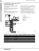
2 SQ, SQE, CU 331, and SP SQ, SQE applications Maintaining a constant water table A constant water table can be maintained by adjusting pump performance. It may be important to maintain a constant water table, e.g. in connection with keeping out the groundwater on a building site or water remediation projects. The example shows how to maintain a constant water table by adjusting pump performance. Sensors Level Description Reaction Level sensor (pos. 11) Warning (max.) Desired level Warning (min.
2 SQ, SQE, CU 331, and SP SQ, SQE applications Emptying or filling a tank The SQE pump with CU 300 is ideal for emptying or filling a tank. 5 21 R100 R100 5 29 2 21 3 R100 R100 29 22 Max. (start) 27 11 1 Min. (stop) Recommended min. 20 inches (0.5 m) 11 22 2 Recommended min. 20 inches (0.5 m) 3 30 31 Fig. 9 Pos.
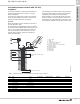
2 SQ, SQE, CU 331, and SP SQ, SQE applications Pumping from one tank to another The SQE pump is ideal for pumping water from one tank to another. Sensors Level Light indication on CU 300 Description Level sensor (pos. 11, tank at top) Max. (stop) Min. (start) Green indicator light When the water has reached in on/off button is this level, the pump stops. flashing. Green indicator light When the water has dropped in on/off button is to this level, the pump starts. permanently on. Level sensor (pos.
2 SQ, SQE, CU 331, and SP Using the R100 and the CU 300 enables change of the motor speed and thereby setting of the pump to a specific performance. The software program "SQE Speed Calculation" has been developed for the calculation of the speed in order to obtain the required flow rate and head. SQ, SQE applications Setting of operating parameters Dry-running protection The value Pcut-out, ensuring dry-running protection, is factory-set for the SQE pump.
2 SQ, SQE, CU 331, and SP SQ, SQE applications SQE with manual speed control Functioning and benefits Furthermore, dedicated installations saves the costs of assembling and dismantling the installation. Important: Through dedicated installation the transfer of contamination from one monitoring well to another is avoided. Manual speed control of the SQE pumps is possible by means of R100 and an SPP 1 potentiometer. This application is especially suitable for sampling from groundwater monitoring wells.
3 SQ, SQE, CU 331, and SP H [m] H [ft] Performance range 3.
4 SQ, SQE, CU 331, and SP SQ, SQE installation 4. SQ, SQE installation The SQ and SQE may be installed vertically, horizontally or in any position in between. Note: The pump must not fall below the horizontal level in relation to the motor.
5 SQ, SQE, CU 331, and SP Sizing and selection 5. Sizing and selection System sizing guide Step 1 Calculate minimum head requirements at no flow conditions: Hmax (required) = dynamic head + system pressure (in feet) + above grade elevation + friction loss Column 2 Shutoff head (0 gpm) @ 3000 rpm min. speed Head @ rated gpm @ 10700 rpm max.
6 SQ, SQE, CU 331, and SP Cable sizing 6. Cable sizing Cable sizing chart Motor rating Copper wire size (AWG) Volts Hp Amps 14 12 10 8 6 4 2 115 0.5 12 140 220 360 550 880 1390 2260 230 230 230 230 0.5 0.75 1 1.5 5.2 8.4 11.2 12 640 400 300 280 1000 620 460 430 1660 1030 770 720 2250 1580 1190 1110 4060 2510 1890 1760 3970 2980 2780 4850 4530 Cable length in feet. Note: shaded values do not apply when using a CU 301 as its max. recommended cable length is 650 ft.
7 SQ, SQE, CU 331, and SP SQ, SQE curve charts 7. SQ, SQE curve charts 5 SQ, SQE H [m] 250 H [ft] 800 5 SQ 5 SQE -450 ISO 9906 Annex A -410 700 200 -360 600 -320 150 500 -270 -230 400 100 -180 300 -140 200 -90 50 100 0 0 0 H [m] 1 2 3 4 5 6 Q [US GPM] 2 3 4 5 6 Q [US GPM] H [ft] 24 4 16 2 8 0 0 NPSH 0 0.0 1 0.4 0.8 1.2 1.
7 SQ, SQE, CU 331, and SP SQ, SQE curve charts 10 SQ, SQE H [m] H [ft] 10 SQ 10 SQE 550 160 ISO 9906 Annex A -330 500 140 120 450 -290 400 -240 350 100 -200 300 80 60 250 -160 200 -110 150 40 100 20 0 50 0 0 H [m] 8 1 2 3 4 5 6 7 8 9 10 11 12 13 Q [US GPM] 3 4 5 6 7 8 9 10 11 12 13 Q [US GPM] H [ft] 30 20 0 10 NPSH 0 0 0.0 20 1 2 0.4 0.8 1.2 1.6 2.0 2.4 2.8 3.
7 SQ, SQE, CU 331, and SP H [m] H [ft] 500 SQ, SQE curve charts 15 SQ, SQE 15 SQ 15 SQE -290 ISO 9906 Annex A 450 -250 120 400 -220 350 -180 300 80 -150 250 200 -110 150 40 -70 100 50 0 0 0 H [m] 8 2 4 6 8 10 12 14 16 18 Q [US GPM] 4 6 8 10 12 14 16 18 Q [US GPM] H [ft] 30 20 0 10 NPSH 0 0 0 2 1 2 3 4 Q [m³/h] TM04 7465 2010 4 21
7 SQ, SQE, CU 331, and SP SQ, SQE curve charts 22 SQ, SQE H [m] H [ft] 22 SQ 22 SQE 360 ISO 9906 Annex A -220 100 320 -190 280 80 240 60 -160 200 -120 160 40 120 -80 80 20 -40 40 0 0 0 H [m] 8 4 8 12 16 20 24 28 Q [US GPM] 8 12 16 20 24 28 Q [US GPM] H [ft] 30 20 0 10 NPSH 0 0 0 22 4 2 4 6 Q [m³/h] TM04 7466 2010 4
7 SQ, SQE, CU 331, and SP H [m] H [ft] 30 SQ 30 SQE 220 60 SQ, SQE curve charts 30 SQ, SQE ISO 9906 Annex A -130 200 180 50 160 140 -90 40 120 30 100 80 20 10 -40 60 40 20 0 0 0 H [m] 8 4 8 12 16 20 24 28 32 36 Q [US GPM] 8 12 16 20 24 28 32 36 Q [US GPM] H [ft] 30 20 0 10 NPSH 0 0 0 4 2 4 6 8 Q [m³/h] TM04 7467 2010 4 23
8 SQ, SQE, CU 331, and SP SQ, SQE technical data 8.
8 SQ, SQE, CU 331, and SP Full load amps Pump type Hp Overload amps 230 V 115 V 230 V 115 V Min. well diameter Voltage SQ, SQE technical data Motor data Discharge 5SQE05-90 5SQE05-140 5SQE05-180 5SQE07-230 5SQE07-270 5SQE07-320 5SQE10-360 5SQE10-410 5SQE15-450 1/2 1/2 1/2 3/4 3/4 3/4 1 1 1 1/2 230 V / 115 V 230 V / 115 V 230 V / 115 V 230 V 230 V 230 V 230 V 230 V 230 V 2.1 2.9 3.7 4.6 5.3 6.2 7.2 8.1 9.2 4.2 6.0 7.
8 SQ, SQE, CU 331, and SP SQ, SQE technical data Dimensions and weights SQ, SQE Dimensions in inches Model 26 Hp A B C D E Approx. ship. wt. 30.4 30.4 31.5 33.6 33.6 34.6 38.2 38.2 39.3 19.8 19.8 19.8 19.8 19.8 19.8 21.3 21.3 21.3 10.6 10.6 11.6 13.7 13.7 14.8 16.9 16.9 18.0 2.6 2.6 2.6 2.6 2.6 2.6 2.6 2.6 2.6 2.9 2.9 2.9 2.9 2.9 2.9 2.9 2.9 2.
9 SQ, SQE, CU 331, and SP SQ, SQE construction 9.
9 SQ, SQE, CU 331, and SP SQ, SQE construction SQ, SQE material specification Pump Pos.
9 SQ, SQE, CU 331, and SP SQ, SQE construction 6 1 2 3 4 bar 5.0 4.5 4.0 3.5 3.0 2.5 2.0 R 100 5 TM03 3426 0406 R100 Fig. 15 CU 301 control unit Operating relay entry Power supply entry Pressure sensor entry Submersible drop cable entry TM02 3427 0406 The CU 301 is a control and communication unit developed especially for the SQE submersible pumps in constant-pressure applications.
9 SQ, SQE, CU 331, and SP SQ, SQE construction R100 menu structure for CU 301 control unit Start Setting Contrast Light 0. General 1. Operation USB version only 2. Status 3. Installation 1.1 2.1 3.1 1.2 2.2 3.2 1.3 2.3 3.3 1.4 2.4 3.4 1.5 2.5 3.5 1.6 2.6 3.6 1.7 3.7 1.8 3.8 3.9 Note: This menu is an example, not the factory setting. 3.
9 SQ, SQE, CU 331, and SP SQ, SQE construction R100 menus for CU 301 0. General 1. Operation 1.1 1.2 1.3 Setpoint setting Selection of operating mode Alarm indication. 2. Status The 2.1 2.2 2.3 2.4 2.5 indication of: Actual operating mode Actual pressure Actual motor speed Actual motor temperature Actual power input and accumulated motor power consumption 2.6 Accumulated number of operating hours and accumulated number of starts. 3. Installation 3.1 3.2 3.3 3.4 3.5 3.6 3.7 3.
9 SQ, SQE, CU 331, and SP R100 IR communication Fig. 18 CU 300 control unit with R100 Extra cable entries Power supply entry Wireless infrared remote control of the CU 300 is possible by means of the R100. Using the R100, it is possible to monitor and change the operating parameters, see the R100 menu structure on page 33. The R100 is a valuable tool in case fault finding is required. 32 Sensor entries Submersible drop cable entry TM01 2761 4801 Fieldbus entry Fig.
9 SQ, SQE, CU 331, and SP SQ, SQE construction R100 menu structure for the CU 300 Start Setting Contrast Light 0. General 1. Operation 2. Status 3. Limits 4. Installation 4.1 1.1 2.1 1.2 2.2 3.2 4.2 1.3 2.3 3.3 4.3 1.4 2.4 3.4 4.4 1.5 2.5 3.5 4.5 1.6 2.6 3.6 4.6 1.7 2.7 3.7 4.7 1.8 2.8 3.8 4.8 2.9 3.9 4.9 3.10 4.10 3.1 USB version only Note: This menu is an example, not the factory setting. 3.11 3.
9 SQ, SQE, CU 331, and SP SQ, SQE construction R100 menus for CU 300 4. Installation 0. General 4.1 4.2 4.3 4.4 4.5 1. Operation 1.1 1.2 1.3 Setpoint setting Selection of operating mode Alarm indication. 2. Status The 2.1 2.2 2.3 2.4 2.5 indication of: Actual operating mode Actual and external setpoint Actual motor temperature Actual motor speed Actual power input and accumulated motor power consumption 2.6 Accumulated number of operating hours and accumulated number of starts 2.
9 SQ, SQE, CU 331, and SP Accumulated number of operating hours and number of starts SQ, SQE construction Examples of R100 displays Menu OPERATION Setpoint setting 1.1 From factory, the pump is set to maximum speed, 10,700 rpm. R100 makes it possible to reduce the pump speed by changing the setpoint. The speed can be set to 3,000 - 10,700 rpm, at 100 rpm intervals. The unit of the setpoint is automatically changed according to the unit of the sensor connected to sensor input 1.
10 SQ, SQE, CU 331, and SP CU331SP variable frequency drive 10. CU331SP variable frequency drive Features User interface The user interface offers these possibilities: • Local operation via a control panel with graphic display where the menu structure is based on the well-known system from Grundfos E-pumps. • Monitoring of operating status via indicator lights and signal relays. • Display of alarm or warning and logging of the last five alarms and warnings.
10 SQ, SQE, CU 331, and SP Identification Nameplate CU331SP variable frequency drive CU331SP performance range H [ft] The CU331SP can be identified by means of the nameplate. An example is shown below. 2000 1500 5 Hp 1000 800 3 Hp 600 500 2 Hp 400 SQE 200 150 100 2 Hp 80 60 50 Fig. 22 Example of nameplate 40 2 4 6 8 10 Key Description T/C: Prod. no: CU-331 (product name) Product number (98370280) Serial number (000201H462) The last four digits indicate the production date.
10 SQ, SQE, CU 331, and SP CU331SP variable frequency drive CU331SP menu overview START-UP GUIDE 1/11 2/11 0. GENERAL 1. OPERATION 2. STATUS 3. INSTALLATION 0.1 1.1 2.1 3.1 0.2 1.2 2.2 3.2 1.3 2.3 3.3 1.4 2.4 3.4 1.5 - 1.9 2.5 3.5 3/11-7/11 Automatic or manual setting of the direction of rotation 8/11 2.6 9/11-10/11 Automatic setting of Stop and Dry-run functions 11/11 1.10-1.14 2.7 2.11 2.12 Fig.
Operating modes Constant pressure with stop function These operating modes can be selected with the CU331SP: • Normal • Stop • Min. • Max. The operating modes can be set without changing the setpoint setting. The outlet pressure is kept constant at high flow rate (Q > Qmin). On/off operation at low flow rate. See fig. 25. The pump operates in constant pressure mode. Qmin The pump has been stopped by user.
10 SQ, SQE, CU 331, and SP CU331SP variable frequency drive Operating conditions for the stop function Setting the direction of rotation It is only possible to use the stop function if the system incorporates a pressure sensor, a non-return valve and a diaphragm tank. The non-return valve must always be installed before the pressure sensor. Diaphragm tank Pressure sensor The start-up guide is started the first time the CU331SP is connected to supply voltage.
Operating hours CU331SP installation The value of operating hours is an accumulated value calculated from the pump's startup date and cannot be reset. No additional sensor is required. Mechanical installation Sensor display will show the actual pressure as received from the pressure transducer. The individual CU331SP cabinet sizes are characterized by their enclosures. The table in section CU331SP technical data on page 49 shows the relationship of enclosure class and enclosure type.
10 SQ, SQE, CU 331, and SP CU331SP electrical connection CU331SP variable frequency drive Space requirements and air circulation TM03 8859 2607 CU331SP units can be mounted side by side, but as a sufficient air circulation is required for cooling these requirements must be met: • Sufficient free space above and below the CU331SP • Ambient temperature up to 122°F (50 °C) • Hang the CU331SP directly on the wall, or fit it with a back plate. See fig. 29. Fig.
Protection against overcurrent Mains connection The CU331SP has an internal overcurrent protection for overload protection on the motor output. Check that mains voltage and frequency correspond to the values on the nameplate of the CU331SP and the motor. Protection against mains voltage transients The CU331SP is protected against mains voltage transients according to EN 61800-3, second environment. Mains and motor connection The supply voltage and frequency are marked on the CU331SP nameplate.
10 SQ, SQE, CU 331, and SP 0/4-20 mA As a precaution, signal cables must be separated from other groups by reinforced insulation in their entire lengths. If no external on/off switch is connected, short-circuit terminals 18 and 20 using a short wire. RS-485 A GND Sensor 1 TM05 5802 3913 Jumper wire GND Start/stop Operation is only possible when the terminals 18 and 20 are connected, for instance by means of an external on/off switch or a short wire.
Setting the analog input 54 Access to signal terminals The contact A54 is positioned behind the control panel and is used for setting the signal type of the analog input. The factory setting of the inputs is voltage signal "U". This setting must be changed to "I" prior to starting the CU331SP. Be sure the power supply is switched off. All signal terminals are behind the terminal cover of the CU331SP front. Remove the terminal cover as shown in fig. 39.
10 SQ, SQE, CU 331, and SP Fig. 42 Terminals for signal relays (normal state, not activated) Terminal C1 NO 1 NC 1 C2 NO 2 NC 2 Function Common Normally open contact Normally closed contact Signal relay TM03 9008 2807 The signal relays on the CU331SP are predefined as follows: Relay 1: Pump running Relay 2: Alarm TM02 1325 0901 TM03 8801 2507 C2 NC 2 NO 2 This section gives guidelines for good practice when installing the CU331SP. Follow these guidelines to meet EN 61800-3, first environment.
10 SQ, SQE, CU 331, and SP To protect itself from AC line voltage disturbances, the CU331SP monitors the input power supply and interrupts drive operation in the event of phase loss or imbalance. Transients on the AC line are suppressed by MOVs as well as zener diodes for extreme transients. The CU331SP meets VDE 0160 (European standard - 2.3 x line voltage for 1.3 msec) for transient protection. The control panel is used for local setting of the CU331SP.
10 SQ, SQE, CU 331, and SP Warning and alarm list The operating condition of the pump is indicated by the indicator lights on the front of the control panel. See fig. 46. The table shows the function of the indicator lights. On (green) Function The pump is running or has been stopped by a stop function. If flashing, the pump has been stopped by the user (CU331SP menu), external start/stop or bus. Off (orange) The pump has been stopped with the on/off button.
10 SQ, SQE, CU 331, and SP CU331SP technical data CU331SP variable frequency drive Terminal tightening torques Tightening torque [ft-lb] Enclosure Enclosure All CU331SP enclosures are size B1. The enclosure rating can be either IP55 / TYPE 12 or IP66 / TYPE 4X. B1 Mains Motor Earth Relay 1.3 1.3 2.2 0.
10 SQ, SQE, CU 331, and SP Sound pressure level CU331SP variable frequency drive Motor output (U, V, W) Output voltage 0-100 % Output frequency 0-60 Hz Switching on output 1) 1) Not recommended Output voltage in % of supply voltage. RS-485 GENIbus connection Terminal number 68 (A), 69 (B), 61 GND (Y) The RS-485 circuit is functionally separated from other central circuits and galvanically separated from the supply voltage (PELV).
10 SQ, SQE, CU 331, and SP 280 260 240 220 200 180 160 140 120 100 80 60 40 20 0 55 Hz 40 Hz 30 Hz 600 160 1 2 3 4 0.5 5 6 7 Q [US GPM] 1.0 Q [m³/h] 60 Hz 55 Hz 700 650 180 600 50 Hz 550 45 Hz 500 140 450 120 400 40 Hz 350 35 Hz 300 80 250 60 200 0 30 Hz 150 100 50 0 0 120 400 2 3 0.5 4 5 6 1.0 7 8 9 10 Q [US GPM] 1.5 Q [m³/h] H [ft] 550 16S20-18 60 Hz 160 500 55 Hz 50 Hz 140 450 120 400 55 Hz 50 Hz 500 450 1 0.
10 SQ, SQE, CU 331, and SP 90 340 70 60 60 320 55 300 50 55 Hz 280 80 25S20-11 60 Hz 260 45 240 40 220 35 45 Hz 180 50 40 30 160 40 Hz 140 120 20 10 H [ft] 40 130 80 70 35 Hz 5 4 6 Q [m³/h] TM05 6414 5012 2 12 16 20 24 28 32 36 Q [US GPM] 120 H [ft] 30 100 4 6 8 10 Q [m³/h] 75S20-3 60 Hz 55 Hz 80 70 50 Hz 60 45 Hz 70 15 40 Hz 50 50 40 Hz 40 35 Hz 10 30 Hz 35 Hz 30 30 Hz 30 20 5 20 10 0 10 20 30 40 50 60 70 80 90 Q [US GPM] 5 10 15 Q [m³/h]
10 400 1300 H [m] 5S30-48ds 60 Hz 300 280 1200 350 1100 300 55 Hz 1000 50 Hz 250 200 800 700 40 Hz 500 0 300 35 Hz 30 Hz 80 250 30 Hz 60 200 150 40 0 1 2 0.5 4 5 6 7 Q [US GPM] 1.
10 SQ, SQE, CU 331, and SP 80 260 H [m] 40S30-9 60 Hz 50 240 45 70 220 60 55 Hz 50 200 50 Hz 35 160 30 45 Hz 40 25 40 Hz 20 100 35 Hz 80 20 10 15 30 Hz 10 40 5 20 0 0 H [m] 50 45 35 30 20 15 170 5 4 6 8 10 Q [m³/h] 100 45 Hz 80 40 Hz 70 60 35 Hz 50 30 Hz 30 20 0 400 130 120 300 50 Hz 110 5 10 15 Q [m³/h] 10S50-48ds 60 Hz 1300 1200 350 55 Hz 10 20 30 40 50 60 70 80 90 Q [US GPM] H [ft] 1400 150 55 Hz 1100 1000 50 Hz 900 100 250 45 Hz 80
10 450 1700 350 300 200 150 1100 1500 55 Hz 300 1300 50 50 Hz 250 1100 1000 45 Hz 200 800 150 600 35 Hz 500 100 30 Hz 300 50 200 2 4 0 800 220 180 600 2 Q [m³/h] 120 400 55 Hz 60 200 90 80 70 45 Hz 60 35 Hz 300 30 Hz 200 0 2 4 H [ft] 360 6 8 10 12 14 16 18 20 22 Q [US GPM] 1 2 3 40S50-12 60 Hz 340 Q [m³/h] 320 300 55 Hz 260 50 Hz 240 220 200 45 Hz 180 50 40 Hz 40 35 Hz 30 30 Hz 20 150 10 0 0 4 8 2 12 16 20 24 28 32 36 Q [US GPM] 4
10 SQ, SQE, CU 331, and SP 110 100 90 80 70 60 50 40 30 20 10 0 55 Hz 60 90 300 50 45 Hz 40 70 60 40 30 35 Hz 20 30 Hz 10 5 10 15 20 25 30 35 40 45 50 55 60 Q [US GPM] 2 4 6 8 10 Q [m³/h] 60S50-9 60 Hz 10 0 80 35 Hz 60 30 Hz 40 0 10 20 30 40 50 60 70 80 90 Q [US GPM] 0 H [m] H [ft] 80 260 5 10 15 Q [m³/h] 75S50-8 60 Hz 70 55 Hz 60 220 50 Hz 200 55 Hz 220 240 200 50 Hz 180 50 160 45 Hz 45 Hz 160 40 140 30 35 Hz 100 140 120 40 Hz 40 Hz 100 35 Hz 8
11 SQ, SQE, CU 331, and SP Accessories 11. Accessories CU 301 Constant Pressure System Description Product number 96438895 TM04 7509 2110 Constant Pressure Kit (CU 301 and Transducer) CU 300 Status Box & R100 Description Product number CU300 Status Box 96422776 TM04 7508 2110 Description Product number R100 (for wireless infrared communication with the CU 301 / CU 300) 96615297 SQ, SQE flow sleeves 100 max.
12 SQ, SQE, CU 331, and SP SP introduction 12. SP introduction Introduction Applications The Grundfos SP range of submersible pumps is renowned for high efficiency and reliability. Made entirely of corrosion resistant stainless steel, SP pumps are ideal for a wide variety of applications. Grundfos SP pumps represent state-of-the-art hydraulic design.
A wide pump range Pump design Grundfos offers energy-efficient SP submersible pumps with a performance range of up to 1,400 gpm and 2,100 ft of head. The pump range consists of many pump sizes, and each pump size is available with an optional number of stages to match any duty point. Grundfos SP submersible pumps feature components that contribute to the superior performance and durability of the range.
12 SQ, SQE, CU 331, and SP Stop ring All pumps are equipped with a reliable check valve in the valve casing preventing back flow in connection with pump stoppage. Furthermore, the short closing time of the check valve means that the risk of destructive water hammer is reduced to a minimum. The valve casing is designed for optimum hydraulic properties to minimize the pressure loss across the valve and thus to contribute to the high efficiency of the pump. Note: As shown in fig.
12 SQ, SQE, CU 331, and SP SP introduction Grundfos submersible motors Grundfos offers a complete submersible motor range in different voltages. For an overview of motor types, sizes and voltages, see page 131. • MS 402 is designed for the domestic ground water market and covers outputs. • The MS 4000 and MS 6000C series are designed for use in a variety of applications in water supply.
12 SQ, SQE, CU 331, and SP SP introduction Overtemperature protection Built-in cooling chambers Accessories for protection against overtemperature are available for both Grundfos MS and MMS submersible motors. When the temperature becomes too high, the protection device will cut out so damage to the pump and motor can be avoided. Restart of the motor after cut-out can be achieved in two ways: • manual restart • automatic restart.
12 SQ, SQE, CU 331, and SP SP introduction Shaft seal MS 402 The shaft seal is of the lip seal type characterized by low friction against the rotor shaft. The rubber material offers good wear resistance, good elasticity and resistance to particles, and it is approved for use in drinking water. MS 4000 Ceramic/tungsten carbide materials provide the MS shaft seals with optimum sealing, optimum wear resistance and long life. MS 6000C TM00 7306 0412 The MS 6000C shaft seal material is SiC/SiC.
12 SQ, SQE, CU 331, and SP SP introduction Identification MS 6000C Example pump: MS 6000CQFT40 3 x 460/60 25 Hp Type key, SP pumps Description Example 475 S 500 - 5- A MS 6000C Q F B Rated flow rate in gpm Motor type Type range Stainless steel parts of material S = AISI 304 N = AISI 316 R = AISI 904L Material type R Hp of motor T40 3x 460/60 25 Hp = AISI 304 Stainless Steel (EN 1.4301) = AISI 904L stainless steel (EN 1.
13 SQ, SQE, CU 331, and SP SP product overview 13.
13 SQ, SQE, CU 331, and SP SP product overview Pump range Type 5S 10S 16S 25S 35S 45S 62S 77S 85S 150S 230S 300S 385S 475S 625S 800S 1100S AISI 304 stainless steel AISI 316 stainless steel AISI 904L stainless steel ● ● ● ● ● ● ● ● ● ● ● ● ● ● ● ● ● ● ● ● ● ● ● ● ● ● ● ● ● ● ● ● ● 1" 1.25" 1.25" 1.5" 1.
14 SQ, SQE, CU 331, and SP Sectional drawing, SP pump 4" spline shaft SP construction 14. SP construction Material specification Standard N-version R-version Pos. Component Material [AISI (EN)] (SP 5S - 25S) 1 2 7 8 9 12 14 16 17 304 (1.4301) 304 (1.4301) 316 (1.4401) 316 (1.4401) 904L (1.4539) 904L (1.4539) 304 (1.4301) 304 (1.4301) 316 (1.4401) 316 (1.4401) 904L (1.4539) 904L (1.4539) 304 (1.4308) 316 (1.4408) 904L (1.4517) 431 (1.4057) 304 (1.4301) 304 (1.4301) 329 (1.4460) 316 (1.
14 SQ, SQE, CU 331, and SP SP construction Sectional drawing, SP pump 4" smooth shaft Material specification Standard N-version R-version Pos. Component (SP 35S - 77S) [AISI (EN)] 1 2 3 7 8 8a 9 13 14 16 17 TM06 1110 1614 18 Fig. 63 SP pump, 4" smooth shaft (SP 35S - 77S) 68 Material Cast 304 316 904L Valve casing stainless (1.4301) (1.4401) (1.4539) steel Cast 304 316 904L Valve cup stainless (1.4301) (1.4401) (1.
14 SQ, SQE, CU 331, and SP Sectional drawing, SP pump 6" (SP 85S - 300S) SP construction Material specification Standard N-version R-version Pos. Component Material [AISI (EN)] 1 2 7 8 9 13 14 16 17 TM06 1521 1614 18 Stainless 304 316 904L Valve casing steel (1.4301) (1.4401) (1.4539) Stainless 304 316 904L Valve cup steel (1.4301) (1.4401) (1.
14 SQ, SQE, CU 331, and SP SP construction Sectional drawing, SP pump 8" (SP 385S - 475S) Material specification Standard Pos.
14 SQ, SQE, CU 331, and SP Sectional drawing, SP pump 10" (SP 625S - 1100S) Standard Pos. Description Material SP construction Material specification N version [AISI (EN)] Valve casing 304 (1.4301) 316 (1.4401) 304 (1.4301) 304 (1.4301) 304 (1.4301) 304 (1.4301) 301 (1.4310) 304 (1.4301) 304 (1.4301) 304 (1.4301) 304 (1.4301) 316 (1.4401) 316 (1.4401) 316 (1.4401) 316 (1.4401) 316 (1.4401) 316 (1.4401) 316 (1.4401) 316 (1.4401) 316 (1.4401) Stainless steel 304 (1.4301) 316 (1.4401) 304 (1.
14 SQ, SQE, CU 331, and SP SP construction Sectional drawing, MS motors Material specification, MS 402, MS 4000, and MS 6000C motors 1 MS 4000 MS 6000C MS 402 Pos. Part [AISI (EN)] 2 5 1 2 Shaft Shaft seal 3 Motor sleeve 4 Motor end shield 5 Radial bearing 6 Axial bearing Rubber parts Pos. Part 5 6 TM00 7865 2196 4 72 Ceramic Ceramic/carbon NBR 431 NBR/SiC/SiC 304 (1.4301) 304 (1.4301) Ceramic/ tungsten carbide Ceramic/carbon NBR R-version motor 3 Fig.
14 SQ, SQE, CU 331, and SP Sectional drawing, MMS motors SP construction Material specification MMS motors, submersible rewindable versions Pos. Component Material 202 Shaft Steel 220 202a Shaft ends Thrust 203/ bearing 206 Stationary/ rotating part 226 204 205 212 213 202a 204 205 [AISI (EN)] (1.0533) 316/329 Stainless steel (1.4401/1.4460) Hardened 6", 0.
15 SQ, SQE, CU 331, and SP SP operating conditions 15. SP operating conditions Operating conditions Curve conditions Flow rate, Q: 0.44 - 1475 gpm (0.1 - 335 m3/h). Head, H: Maximum 2657 ft (810 m). The conditions below apply to the curves in section 17. SP curve charts and technical data: Maximum liquid temperature General Installation Motor Flow velocity past motor Vertical [°F (°C)] Horizontal [°F (°C)] Grundfos MS 4" and MS 6000C T-40 versions 0.49 fps (0.
16 SQ, SQE, CU 331, and SP H [m] 400 H [ft] How to read the curve charts 16. How to read the curve charts 5S 1300 60 Hz, SF 1.15 -48DS Pump type, number of poles and frequency. ISO 9906 Annex A 1200 350 1100 Number of stages. First figure: number of stages; second figure: number of reduced-diameter impellers. -39DS 300 QH curve for the individual pump. The bold curves indicate the recommended performance range for best efficiency.
17 SQ, SQE, CU 331, and SP SP curve charts and technical data 17. SP curve charts and technical data 4" and larger wells SP 5S (5 gpm) H [m] 400 H [ft] 5S 60 Hz, SF 1.15 1300 -48DS (3 hp) ISO 9906 Annex A 1200 350 1100 -39DS (2 hp) 300 1000 900 250 -31 (1.5 hp) 800 -26 (1.5 hp) 700 200 -22 (1 hp) 600 150 -18 (0.75 hp) 500 400 -13 (0.5 hp) 100 300 -9 (0.5 hp) 200 50 100 0 0 0 1 2 3 4 5 6 7 Q [US GPM] 0.0 P2 [hp] 0.06 0.08 0.04 0.00 0.6 0.8 1.0 1.2 1.
17 SQ, SQE, CU 331, and SP Pump model Nom. Volts head Ph [V] [ft] Dimensions Motor [Hp] A B C [in. (mm)] [in. (mm)] [in. (mm)] D E [in. (mm)] [in. (mm)] Net weight (complete) [lb] SP curve charts and technical data 4" and larger wells - continued SP 5S (5 gpm) / 4 inch motor 5S NPT 5S, motor dia.
17 SQ, SQE, CU 331, and SP SP curve charts and technical data 4" and larger wells - continued SP 7S (7 gpm) H [m] H [ft] 7S 60 Hz, SF 1.15 900 ISO 9906 Annex A -32 (2 hp) 250 800 -26 (1.5 hp) 700 200 600 -19 (1 hp) 150 500 -15 (0.75 hp) 400 100 -11 (0.5 hp) 300 -8 (0.5 hp) 200 50 100 0 0 0 1 2 3 4 5 6 7 8 9 10 Q [US GPM] P2 [hp] 0.0 0.2 0.4 0.6 0.8 1.0 1.2 1.4 0.10 0.06 0.08 0.04 0.06 0.00 2.0 Q [m³/h] Eff [%] 50 40 30 P2 20 0.02 10 0.00 0 0 78 1.8 Eff 0.
17 SQ, SQE, CU 331, and SP Pump model Nom. Volts Motor head Ph [V] [Hp] [ft] Dimensions A B C D E [in. (mm)] [in. (mm)] [in. (mm)] [in. (mm)] [in. (mm)] Net weight (complete) [lb] SP curve charts and technical data 4" and larger wells - continued SP 7S (7 gpm) / 4 inch motor 7S NPT 7S, motor dia.
17 SQ, SQE, CU 331, and SP SP curve charts and technical data 4" and larger wells - continued SP 10S (10 gpm) H [m] H [ft] 10S -58DS (5 hp) 60 Hz, SF 1.15 500 ISO 9906 Annex A 1600 -48DS (5 hp) 1400 400 1200 300 1000 -34 (3 hp) 800 -27 (2 hp) 200 -21 (1.5 hp) 600 -15 (1 hp) 400 -12 (0.75 hp) 100 -9 (0.5 hp) 200 0 -6 (0.5 hp) 0 0 2 4 6 8 10 12 14 Q [US GPM] P2 [hp] 0.0 0.5 1.0 0.10 0.06 0.08 0.04 0.06 0.02 0.00 2.0 2.5 Q [m³/h] Eff [%] 50 Eff 40 30 P2 0.
17 SQ, SQE, CU 331, and SP Nom. Volts Motor Pump model head Ph [V] [Hp] [ft] Dimensions A B C D E [in. (mm)] [in. (mm)] [in. (mm)] [in. (mm)] [in. (mm)] Net weight (complete) [lb] 116 1 10S05-9 174 1 10S07-12 10S10-15 10S15-21 233 291 407 1 1 1 10S05-6 116 1 10S05-9 174 1 10S07-12 10S10-15 233 291 1 1 1 10S15-21 407 230 115 230 230 230 230 .5 .5 .5 .75 1 1.5 ■ ■ ■ ■ ■ ■ 22.05 24.53 24.53 27.60 30.67 37.17 (560) (623) (623) (701) (779) (944) 10.99 (279) 10.99 (279) 10.
17 SQ, SQE, CU 331, and SP SP curve charts and technical data 4" and larger wells - continued SP 16S (16 gpm) H [m] H [ft] 16S 700 -75DS (10 hp) 60 Hz, SF 1.15 2200 ISO 9906 Annex A 600 2000 1800 -56DS (7.5 hp) 500 1600 1400 400 1200 -38 (5 hp) 300 1000 800 -24 (3 hp) 200 600 -18 (2 hp) -14 (1.5 hp) 400 100 -10 (1 hp) -8 (0.75 hp) 200 0 -5 (0.5 hp) 0 0 2 4 6 8 10 12 14 16 18 20 22 Q [US GPM] 0.16 0.5 1.0 1.5 2.0 2.5 3.0 3.5 4.0 H [hp] Q [m³/h] Eff [%] 0.
17 SQ, SQE, CU 331, and SP Pump model Nom. Volts head Ph [V] [ft] Dimensions Motor [Hp] A B C D E [in. (mm)] [in. (mm)] [in. (mm)] [in. (mm)] [in. (mm)] SP curve charts and technical data 4" and larger wells - continued SP 16S (16 gpm) / 4, 6 inch motors 16S Net weight (complete) [lb] E Rp NPT1 102 1 16S07-8 16S10-10 16S15-14 162 203 284 1 1 1 115 230 230 230 230 .5 .5 .75 1 1.5 ■ ■ ■ ■ ■ 21.26 21.26 24.34 26.58 31.38 (540) (540) (618) (675) (797) 11.03 (280) 11.03 (280) 11.
17 SQ, SQE, CU 331, and SP SP curve charts and technical data 4" and larger wells - continued SP 25S (25 gpm) H [m] H [ft] 25S 500 1600 -52DS (10 hp) 60 Hz, SF 1.15 ISO 9906 Annex A 450 1500 1400 400 1300 1200 -39DS (7.5 hp) 350 1100 300 1000 900 250 -26 (5 hp) 800 700 200 600 150 500 -15 (3 hp) 400 -11 (2 hp) 100 300 -9 (1.5 hp) -7 (1 hp) 200 -5 (0.75 hp) 50 -3 (0.5 hp) 100 0 0 0 5 10 15 20 25 30 35 40 Q [US GPM] 0.
17 SQ, SQE, CU 331, and SP Pump model Nom. Volts Motor head Ph [V] [Hp] [ft] Dimensions A B C [in. (mm)] [in. (mm)] [in. (mm)] D E [in. (mm)] [in. (mm)] SP curve charts and technical data 4" and larger wells - continued SP 25S (25 gpm) / 4, 6 inch motors 25S Net weight (complete) [lb] E Rp NPT1 60 1 25S07-5 25S10-7 25S15-9 99 139 179 1 1 1 115 230 230 230 230 .5 .5 .75 1 1.5 ■ ■ ■ ■ ■ 19.61 19.61 21.86 24.10 27.25 (498) (498) (555) (612) (692) 11.03 (280) 8.59 (218) 11.03 (280) 8.
17 SQ, SQE, CU 331, and SP SP curve charts and technical data 4" and larger wells - continued SP 35S (35 gpm) + >P@ + >IW@ 63 6 KS +] 6) KS ,62 *UDGH % KS KS KS KS KS KS KS KS KS KS KS KS KS KS KS
17 SQ, SQE, CU 331, and SP Pump model Nom. head Ph [ft] Dimensions Volts [V] Motor [Hp] A B C [in. (mm)] [in. (mm)] [in. (mm)] D E [in. (mm)] [in.
17 SQ, SQE, CU 331, and SP SP curve charts and technical data 4" and larger wells - continued SP 35S (35 gpm) / 6 inch motor Pump model Nom. head Ph [ft] Dimensions Volts [V] Motor [Hp] A B C [in. (mm)] [in. (mm)] [in. (mm)] D E [in. (mm)] [in. (mm)] Net weight (complete) [lb] 35S NPT 35S75-22 487 35S75-25 554 35S75-28 621 35S100-31 688 35S100-34 755 35S100-38 844 208-230 460 575 208-230 460 575 208-230 460 575 208-230 460 575 208-230 460 575 208-230 460 575 7.5 7.5 7.5 7.
17 SQ, SQE, CU 331, and SP Pump model Nom. head Ph [ft] Dimensions Volts [V] Motor [Hp] A B C [in. (mm)] [in. (mm)] [in. (mm)] D E [in. (mm)] [in.
17 SQ, SQE, CU 331, and SP SP curve charts and technical data 4" and larger wells - continued SP 45S (45 gpm) + >P@ + >IW@ 63 6 KS +] 6) ,62 *UDGH % KS KS KS KS KS KS KS KS KS KS KS KS KS KS KS
17 SQ, SQE, CU 331, and SP Pump model Nom. head Ph [ft] Dimensions Volts [V] Motor [Hp] A B C [in. (mm)] [in. (mm)] [in. (mm)] D E [in. (mm)] [in.
17 SQ, SQE, CU 331, and SP SP curve charts and technical data 4" and larger wells - continued SP 45S (45 gpm) / 6 inch motor Pump model Nom. head Ph [ft] Volts [V] Moto r [Hp] Dimensions A B C [in. (mm)] [in. (mm)] [in. (mm)] D E [in. (mm)] [in.
17 SQ, SQE, CU 331, and SP Pump model Nom. head Ph [ft] Dimensions Volts [V] Motor [Hp] A B C [in. (mm)] [in. (mm)] [in. (mm)] D E [in. (mm)] [in. (mm)] Net weight (complete) [lb] SP curve charts and technical data 4" and larger wells - continued SP 45S (45 gpm) / 6 inch motor 45S NPT 45S250-54DS 1376 1453 1529 25 ▲ 161.54 (4103) 31.78 (807) 129.77 (3296) 5.50 (140) 5.50 (140) 3 575 25 ▲ 161.54 (4103) 31.78 (807) 129.77 (3296) 5.50 (140) 5.50 (140) 267.6 208-230 25 ▲ 167.
17 SQ, SQE, CU 331, and SP SP curve charts and technical data 4" and larger wells - continued SP 62S (62 gpm) + >P@ + >IW@ 63 6 +] 6) KS ,62 *UDGH % KS KS KS KS KS KS KS KS KS KS KS (II > @
17 SQ, SQE, CU 331, and SP Pump model Nom. head Ph [ft] Dimensions Volts [V] Motor [Hp] A B C [in. (mm)] [in. (mm)] [in. (mm)] D E [in. (mm)] [in.
17 SQ, SQE, CU 331, and SP SP curve charts and technical data 4" and larger wells - continued SP 62S (62 gpm) / 6 inch motor Pump model Nom. head Ph [ft] Dimensions Volts [V] Motor [Hp] A B C [in. (mm)] [in. (mm)] [in. (mm)] D E [in. (mm)] [in. (mm)] Net weight (complete) [lb] 62S NPT 3 62S75-14 285 3 3 3 62S75-17 347 409 450 491 119.3 575 7.5 ▲ 76.70 (1948) 23.51 (597) 53.19 (1351) 5.50 (140) 5.50 (140) 119.3 208-230 7.5 ▲ 85.56 (2173) 23.51 (597) 62.05 (1576) 5.50 (140) 5.
17 SQ, SQE, CU 331, and SP + >P@ + >IW@ SP curve charts and technical data 4" and larger wells - continued SP 77S (77 gpm) 63 6 +] 6) ,62 *UDGH % KS KS KS KS KS KS KS KS KS KS (II > @
17 SQ, SQE, CU 331, and SP SP curve charts and technical data 4" and larger wells - continued SP 77S (77 gpm) / 4 inch motor Pump model Nom. head Ph [ft] Dimensions Volts [V] Motor [Hp] A B C [in. (mm)] [in. (mm)] [in. (mm)] D E [in. (mm)] [in.
17 SQ, SQE, CU 331, and SP Pump model Nom. head Ph [ft] Dimensions Volts [V] Motor [Hp] A B C [in. (mm)] [in. (mm)] [in. (mm)] D E [in. (mm)] [in. (mm)] Net weight (complete) [lb] SP curve charts and technical data 4" and larger wells - continued SP 77S (77 gpm) / 6 inch motor 77S NPT 77S75-12 230 3 3 3 77S75-15 289 329 115.8 575 .75 ▲ 70.79 (1798) 23.51 (597) 47.29 (1201) 5.50 (140) 5.50 (140) 115.8 208-230 .75 ▲ 79.65 (2023) 23.51 (597) 56.15 (1426) 5.50 (140) 5.50 (140) 121.
17 SQ, SQE, CU 331, and SP SP curve charts and technical data 6" and larger wells SP 85S (85 gpm) H [m] H [ft] 85S -18 (20 hp) 60 Hz, SF 1.15 -17 (20 hp) 900 ISO 9906 Annex A -16 (20 hp) 250 -15 (20 hp) 800 -14 (20 hp) -13 (15 hp) 700 200 -12 (15 hp) 600 -11 (15 hp) -10 (15 hp) 150 500 -9 (10 hp) -8 (10 hp) 400 -7 (10 hp) -6 (7.5 hp) 100 300 -5 (7.5 hp) -4 (5 hp) 200 -3 (5 hp) 50 -2 (3 hp) 100 -1 (1.
17 SQ, SQE, CU 331, and SP + >P@ + >IW@ SP curve charts and technical data 6" and larger wells - continued SP 85S (85 gpm) 6 +] 6) ,62 $QQH[ $ KS KS KS KS KS KS KS KS KS KS KS KS KS KS KS + >IW@ 4 >86 *30@ 4 >Pñ K@ (II > @
17 SQ, SQE, CU 331, and SP Pump model Nom. head [ft] Dimensions Volts Ph [V] Motor [Hp] A B C [in. (mm)] [in. (mm)] [in. (mm)] D E [in. (mm)] [in. (mm)] Net weight (complete) [lb] 85S E 85S - Motor dia. 4 inch, 3 wire motor, 60 Hz, rated flow 85 gpm (3" NPT) 74 85S50-3 114 85S50-4 154 85S75-5 194 85S75-6 234 85S100-7 85S100-8 85S100-9 274 314 353 ■ ■ ■ ● ● ● ● ● ● ● ● ● ● ● ● ● ● ● ● 28.04 (712) 26.46 (672) 26.46 (672) 37.88 (962) 33.12 (841) 33.12 (841) 44.22 (1123) 40.
17 SQ, SQE, CU 331, and SP Pump model Nom. Volts Motor head Ph [V] [Hp] [ft] Dimensions A B C [in. (mm)] [in. (mm)] [in. (mm)] D E [in. (mm)] [in.
17 SQ, SQE, CU 331, and SP SP curve charts and technical data 6" and larger wells - continued SP 150S (150 gpm) H [m] H [ft] 150S 950 -17 (30 hp) 60 Hz, SF 1.15 280 900 260 240 ISO 9906 Annex A -16 (30 hp) 850 -15 (30 hp) 800 -14 (25 hp) 750 -13 (25 hp) 220 700 -12 (25 hp) 200 180 650 -11 (20 hp) 600 -10 (20 hp) 550 160 140 120 500 -9 (20 hp) 450 -8 (15 hp) 400 -7 (15 hp) 350 -6 (15 hp) 100 300 80 -5 (10 hp) 250 -4 (7.5 hp) 60 200 -3 (7.
17 SQ, SQE, CU 331, and SP H [m] H [ft] SP curve charts and technical data 6" and larger wells - continued SP 150S (150 gpm) 150S 700 60 Hz, SF 1.
17 SQ, SQE, CU 331, and SP SP curve charts and technical data 6" and larger wells - continued SP 150S (150 gpm) / 4 inch motor Pump model Nom. Volts head Ph [V] [ft] Dimensions Motor [Hp] A B C [in. (mm)] [in. (mm)] [in. (mm)] D E [in. (mm)] [in.
17 SQ, SQE, CU 331, and SP Pump model Nom. Volts Motor head Ph [V] [Hp] [ft] Dimensions A B C [in. (mm)] [in. (mm)] [in. (mm)] D E [in. (mm)] [in.
17 SQ, SQE, CU 331, and SP SP curve charts and technical data 6" and larger wells - continued SP 230S (230 gpm) H [m] H [ft] 230S 160 -8 (25 hp) 60 Hz, SF 1.15 500 ISO 9906 Annex A 140 -7 (25 hp) 450 -7-C (20 h p) 120 400 -6 (20 hp) 350 100 -5 (20 hp) -5-B (15 hp) 300 80 -4 (15 hp) 250 -4-BC (10 hp) 60 200 -3 (10 hp) 150 -3-BB (7.5 hp) -2 (7.
17 SQ, SQE, CU 331, and SP H [m] 450 H [ft] SP curve charts and technical data 6" and larger wells - continued SP 230S (230 gpm) 230S 1500 60 Hz, SF 1.
17 SQ, SQE, CU 331, and SP SP curve charts and technical data 6" and larger wells - continued SP 230S (230 gpm) / 4, 6 inch motor Pump model Nom. Volts head Ph [V] [ft] Dimensions Motor [Hp] A B C [in. (mm)] [in. (mm)] [in. (mm)] D E [in. (mm)] [in.
17 SQ, SQE, CU 331, and SP Pump model Nom. Volts Motor head Ph [V] [Hp] [ft] Dimensions A B C [in. (mm)] [in. (mm)] [in. (mm)] D E [in. (mm)] [in.
17 SQ, SQE, CU 331, and SP SP curve charts and technical data 6" and larger wells - continued SP 300S (300 gpm) H [m] H [ft] 300S 160 60 Hz, SF 1.15 500 ISO 9906 Annex A -7 (25 hp) 140 450 -6 (25 hp) 120 400 -6-B (20 hp) 350 -5 (20 hp) 100 -5-AA (20 hp) 300 -4 (15 hp) 80 250 -4-AA (15 hp) 60 -3 (15 hp) 200 -3-A (10 hp) 150 -2 (7.
17 SQ, SQE, CU 331, and SP H [m] 400 H [ft] SP curve charts and technical data 6" and larger wells - continued SP 300S (300 gpm) 300S 60 Hz, SF 1.
17 SQ, SQE, CU 331, and SP SP curve charts and technical data 6" and larger wells - continued SP 300S (300 gpm) / 4, 6 inch motor Pump model Nom. Volts head Ph [V] [ft] Dimensions Motor [Hp] A B C [in. (mm)] [in. (mm)] [in. (mm)] D E [in. (mm)] [in. (mm)] Net weight (complete) [lb] 300S E Rp NPT Rp 31 300S50-2BB 42 300S75-2 70 300S100-3A 97 230 230 460 230 230 460 230 230 460 230 460 460 3 3 3 5 5 5 5 5 5 7.5 7.5 10 ● ● ● ● ● ● ● ● ● ● ● ● 37.60 (955) 32.84 (834) 32.84 (834) 41.
17 SQ, SQE, CU 331, and SP Nom. Volts Pump model head Ph [V] [ft] Dimensions Motor [Hp] A B C [in. (mm)] [in. (mm)] [in. (mm)] D E [in. (mm)] [in.
17 SQ, SQE, CU 331, and SP SP curve charts and technical data 8" and larger wells SP 385S (385 gpm) H [m] H [ft] 385S 60 Hz, SF 1.15 550 -6-B (40 hp) ISO 9906 Annex A 160 500 -5 (40 hp) 140 450 -5-BB (30 hp) 120 400 -4 (30 hp) 350 -4-B (25 hp) 300 -3 (25 hp) 100 -3-A (20 hp) 80 250 60 200 -2 (18 hp) 150 -2-BA (10 hp) 40 -1 (7.
17 SQ, SQE, CU 331, and SP H [m] 400 H [ft] SP curve charts and technical data 8" and larger wells - continued SP 385S (385 gpm) 385S 60 Hz, SF 1.
17 SQ, SQE, CU 331, and SP SP curve charts and technical data 8" and larger wells - continued SP 385S (385 gpm) / 6, 8, 10 inch motor Pump model Nom. Volts head Ph [V] [ft] Dimensions Motor [Hp] A B C [in. (mm)] [in. (mm)] [in. (mm)] D E [in. (mm)] [in.
17 SQ, SQE, CU 331, and SP H [m] H [ft] SP curve charts and technical data 8" and larger wells - continued SP 475S (475 gpm) 475S 160 60 Hz, SF 1.15 500 ISO 9906 Annex A -5-B (40 hp) 140 450 -4 (40 hp) 120 400 -4-AB (30 hp) 350 100 -3 (30 hp) 300 80 250 -2 (20 hp) 60 200 -2-B (15 hp) 150 40 -1 (10 hp) 100 -1-A (7.
17 SQ, SQE, CU 331, and SP SP curve charts and technical data 8" and larger wells - continued SP 475S (475 gpm) H [m] 400 H [ft] 475S -13 (125 hp) 60 Hz, SF 1.
17 SQ, SQE, CU 331, and SP Nom. Volts Pump model head Ph [V] [ft] Dimensions Motor [Hp] A B C [in. (mm)] [in. (mm)] [in. (mm)] D E [in. (mm)] [in.
17 SQ, SQE, CU 331, and SP SP curve charts and technical data 10" and larger wells SP 625S (625 gpm) H [m] H [ft] 625S -4 (100 hp) 60 Hz, SF 1.
17 SQ, SQE, CU 331, and SP H [m] H [ft] SP curve charts and technical data 10" and larger wells - continued SP 625S (625 gpm) 625S 60 Hz, SF 1.
17 SQ, SQE, CU 331, and SP SP curve charts and technical data 10" and larger wells - continued SP 625S (625 gpm) / 6, 8 inch motors Pump model Nom. Volts head Ph [V] [ft] Dimensions Motor [Hp] A B C [in. (mm)] [in. (mm)] [in. (mm)] D E [in. (mm)] [in. (mm)] 625S Net weight (complete) [lb] E Rp NPT6 95 625S300-2AA 130 625S400-2A 625S400-2 625S500-3AA 625S600-3A 625S600-3 159 194 224 258 292 ▲ ▲ ▲ ▲ ▲ ▲ ▲ ▲ ♦ * * 53.51 53.51 58.63 58.63 67.33 67.33 72.05 72.05 94.02 (1359) 27.
17 SQ, SQE, CU 331, and SP H [m] H [ft] SP curve charts and technical data 10" and larger wells - continued SP 800S (800 gpm) 800S 160 60 Hz, SF 1.
17 SQ, SQE, CU 331, and SP SP curve charts and technical data 10" and larger wells - continued SP 800S (800 gpm) H [m] H [ft] 800S 60 Hz, SF 1.
17 SQ, SQE, CU 331, and SP Pump model Nom. Volts head Ph [V] [ft] Dimensions Motor [Hp] A B C [in. (mm)] [in. (mm)] [in. (mm)] D E [in. (mm)] [in.
17 SQ, SQE, CU 331, and SP SP curve charts and technical data 10" and larger wells - continued SP 1100S (1100 gpm) H [m] H [ft] 1100S -3 (125 hp) 60 Hz, SF 1.
17 SQ, SQE, CU 331, and SP H [m] H [ft] 350 SP curve charts and technical data 10" and larger wells - continued SP 1100S (1100 gpm) 1100S -6 (250 hp) 60 Hz, SF 1.
17 SQ, SQE, CU 331, and SP SP curve charts and technical data 10" and larger wells - continued SP 1100S (1100 gpm) / 6, 8, 10 inch motors Pump model Nom. Volts Motor head Ph [V] [Hp] [ft] Dimensions A B C [in. (mm)] [in. (mm)] [in. (mm)] D E [in. (mm)] [in. (mm)] 1100S Net weight (complete) [lb] E Rp 6 NPT 230 460 460 460 30 30 40 60 ▲ 66.66 (1693) ▲ 66.66 (1693) ▲ 71.38 (1813) † - 1100S300-1A 67 35.56 (903) 31.11 (790) 5.63 (143) 9.30 (236) 35.56 (903) 31.11 (790) 5.63 (143) 9.
18 SQ, SQE, CU 331, and SP SP electrical data 18. SP electrical data Grundfos submersible pump motors - 60 Hz Circuit breaker or fuses Hp Ph Volt [V] Amperage Full load Max. [A] Eff. [%] PF [%] Max. thrust [lb] Product number Start [A] S.F. Std. Delay 4-inch, single-phase, 2-wire motors (control box not required) .5 .5 .75 1 1.5 1 1 1 1 1 115 230 230 230 230 1.60 1.60 1.50 1.40 1.30 35 15 20 25 35 15 7 9 12 15 55.0 34.5 40.5 48.4 62.0 12.0 6.0 8.4 9.8 13.
19 SQ, SQE, CU 331, and SP MP 204 Benefits The MP 204 is an electronic motor protector, designed for the protection of an asynchronous motor or a pump. The motor protector consists of: • a cabinet incorporating transformers and electronics • a control panel with operating buttons and display for reading of data. The MP 204 operates with two sets of limits: • a set of warning limits and • a set of trip limits.
19 SQ, SQE, CU 331, and SP Product numbers Product number Product Description MP 204 Motor protector 96079927 MI 202 Dongle for iPhone 4/4s, iPad, or iPod touch (30 pin connector compatible) 98046376 MI 204 Dongle for iPhone 5/5s, iPad, or iPod touch (lightening connector compatible) 98424092 MI 301 Universal Bluetooth dongle for Android or iOS device 98046408 MI 204 MI204 Kit with MI204 dongle, Apple iPod 5, sleeve and cover 98612711 Functions • • • • • • Phase-sequence monitoring Indi
19 SQ, SQE, CU 331, and SP Accessories Technical data - MP 204 Enclosure class IP20 Ambient temperature -4 °F to +140 °F (-20 °C to +60 °C) Relative air humidity 99 % Voltage range 100-480 VAC Current range 3-999 A Frequency 50 to 60 Hz IEC trip class 1-45 Special Grundfos trip class 0.1 to 30 s Voltage variation - 25 %/+ 15 % of nominal voltage Approvals EN 60947, EN 60335, UL/CSA 508 Marking CE, cUL, C-tick Consumption Max.
19 SQ, SQE, CU 331, and SP Accessories Control functions This table describes the protection provided by MP 204. Control parameters Function Problem Advantages Temperature MS The motor temperature is measured by means of the built-in Tempcon temperature transmitter and a signal is sent to MP 204 via the phase leads. In MP 204 the measured temperature is compared with the factory-set value of 167 °F (75 °C). MMS The motor temperature is measured by means of the Pt100.
19 SQ, SQE, CU 331, and SP Grundfos GO is the mobile tool box for professional users on the go. The Grundfos GO app can be used to establish wireless connection to Grundfos products. Grundfos GO gives you intuitive handheld pump control, and full access to all the Grundfos Online tools on the go. Grundfos GO consists of two Apps: GO Remote and GO CAPS. It is available from Apple App Store and Google Play.
19 SQ, SQE, CU 331, and SP Accessories MI 301 TM05 3890 1612 The MI 301 is a module that connects to an Android or iOS-based smart device via Bluetooth. The MI 301 has a rechargeable Li-ion battery and must be charged separately. Fig. 72 MI 301 Supported devices The smart devices listed below have been tested and are supported by Grundfos GO.
19 SQ, SQE, CU 331, and SP Accessories Connecting pieces The tables below show the range of connecting pieces for connection of thread-to-flange and thread-to-thread. B A TM01 2397 1698 - GrA2555 Thread-to- thread L Fig. 73 Dimensional sketch and photo of connecting piece thread-to-thread Dimensions Product number Type 385S 475S 625S 800S 1100S Connecting piece Thread-to-thread A B L [in. (mm)] 304 stainless steel 316 stainless steel NPT 5 NPT 4 NPT 5 NPT 4 4.
19 SQ, SQE, CU 331, and SP SA-SPM 6 control boxes Application Version SA-SPM 6 control boxes are used as starting units for single-phase, 3-wire motors ranging from 0.5 Hp to 5 Hp (.37 kW to 3.7 kW). SA-SPM 6 from 1.5 Hp to 5 Hp (1.1 kW to 3.7 kW) is available available in two versions, standard and deluxe. The standard version incorporates a motor -protective circuit breaker and thus protects the motor against overload.
19 SQ, SQE, CU 331, and SP Accessories Pt100 The Pt100 sensor offers these features: • Continuous monitoring of the motor temperature • Protection against too high motor temperature. Protecting the motor against too high motor temperature is the simplest and cheapest way of avoiding that motor lifetime is reduced. Pt100 ensures that operating conditions are not exceeded and indicates when it is time for service of the motor.
20 SQ, SQE, CU 331, and SP Energy consumption of submersible pumps Calculation of motor efficiency at duty point The percentage distribution of service life costs of a submersible pump for water supply is: 5 % initial costs (pump) 85 % operating costs / energy consumption 10 % maintenance costs.
21 SQ, SQE, CU 331, and SP Cables 21. Cables Cables for Grundfos 4" submersible motors are available with or without plugs. The submersible drop cable is chosen according to application and type of installation. Standard version: Max. liquid temperature 140 °F (60 °C). Hot water version: Max. liquid temperature 158 °F (70 °C), for short periods up to 194 °F (90 °C) (for MS only).
21 SQ, SQE, CU 331, and SP Cables Cable sizing charts 115 V and 230 V, 1 ph 60 Hz Maximum submersible power cable length (max. cable length in feet - starter to motor) Motor rating AWG copper wire size [ft (m)] [Hp] 14 115 V 1 ph 60 Hz 230 V 1 ph 60 Hz 130 0.33 (40) 100 0.5 (30) 550 0.33 (168) 400 0.5 (122) 300 0.75 (91) 250 1 (76) 190 1.
21 SQ, SQE, CU 331, and SP Cables 200-208 V, 3 Ph 60 Hz Maximum submersible power cable length (max. cable length in feet - starter to motor) Motor rating .5 .75 1 1.5 2 3 200-208 V 3 ph 60 Hz AWG copper wire size [ft (m)] [Hp] 5 7.
21 SQ, SQE, CU 331, and SP Cables 230 V, 3 Ph 60 Hz Maximum submersible power cable length (max. cable length in feet - starter to motor) Motor rating AWG copper wire size [ft (m)] [Hp] 14 230 V 3 ph 60 Hz 930 0.5 (283) 670 0.75 (204) 560 1 (171) 420 1.5 (128) 320 2 (98) 240 3 (73) 140* 5 (43*) 12 1490 (454) 1080 (329) 910 (277) 670 (204) 510 (155) 390 (119) 230 (70) 160* (49*) 7.
21 SQ, SQE, CU 331, and SP Cables 460 V, 3 ph 60 Hz Maximum submersible power cable length (max. cable length in feet - starter to motor) AWG copper wire size [ft (m)] Motor rating [Hp] .5 .75 1 1.5 2 3 5 7.
21 SQ, SQE, CU 331, and SP Cables 575 V, 3 ph 60 Hz Maximum submersible power cable length (max. cable length in feet - starter to motor) Motor rating 5 .75 1 1.5 2 3 5 7.
22 SQ, SQE, CU 331, and SP Friction loss tables 22. Friction loss tables Friction loss table - SCH 40 steel pipe [US gpm] [US gph] .5" .75" 1" ID 0.622" ID 0.824" ID 1.049" 1.25" 1.5" 2" 2.5" 3" 4" ID 1.380" ID 1.610" ID 2.067" ID 2.469" ID 3.068" ID 4.026" 1.2 1.6 2.0 2.4 3.4 4.5 5.8 8.9 14.8 19.5 1.2 1.5 2.3 3.7 4.
Friction loss tables 22 SQ, SQE, CU 331, and SP Friction loss table - SCH 40 PVC pipe [US gpm] [US gph] .5" .75" 1" ID 0.622" ID 0.824" ID 1.049" 1.25" 1.5" 2" 2.5" 3" 4" ID 1.380" ID 1.610" ID 2.067" ID 2.469" ID 3.068" ID 4.026" 1.2 1.4 1.8 2.2 3.0 4.0 5.0 7.6 12.2 15.8 1.1 1.4 2.1 3.4 4.4 2" 2.
23 SQ, SQE, CU331, and SP Grundfos Product Center 23. Grundfos Product Center Grundfos Product Center is an online search and sizing tool to help you make the right choice. http://product-selection.grundfos.com SIZING enables you to size a pump based on entered data and selection choices. REPLACEMENT enables you to find a replacement product. Search results will include information on • the lowest purchase price • the lowest energy consumption • the lowest total life cycle cost.
© Copyright Grundfos Holding A/S 99234929 0217 ECM: 1169375 Grundfos Kansas City 17100 West 118th Terrace Olathe, Kansas 66061 Phone: 913-227-3400 Fax: 913-227-3500 www.grundfos.us Grundfos Canada 2941 Brighton Road Oakville, Ontario L6H 6C9 Canada Phone: +1-905-829-9533 Fax: +1-905-829-9512 www.grundfos.ca Grundfos México Boulevard TLC No. 15 Parque Industrial Stiva Aeropuerto C.P. 66600 Apodaca, N.L. Mexico Phone: 011-52-81-8144 4000 Fax: 011-52-81-8144 4010 www.grundfos.