GRUNDFOS DATA BOOKLET JP PS Jet pumps with pressure switch, 115/230 V, 60 Hz
JP PS Table of contents 1. Product introduction . . . . . . . . . . . . . . . . . . . . 3 Product overview, JP PS Applications . . . . . . . . . Pumped liquids. . . . . . . Features and benefits . . Motor . . . . . . . . . . . . . Performance range . . . . Product range. . . . . . . . Identification. . . . . . . . . 2. . . . . . . . . . . . . . . . . . . . . . . . . . . . . . . . . . . . . . . . . . . . . . . . . . . . . . . . . . . . . . . . . . . . . . . . . . . . . . . . . . . . . . . . .
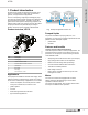
1 JP PS Product introduction 1. Product introduction TM074113 Grundfos JP PS pumps are designed for domestic use to ensure a constant supply of clean water to households, gardens, and light commercial applications. JP PS is a self-priming, single-stage centrifugal jet pump. The pump has excellent suction capacity and is designed for long and trouble-free operation. The built-in ejector with guide vanes ensures optimum self-priming properties.
1 JP PS Product introduction Performance range The performance curves show the performance range of JP PS pumps. H [m] H [ft] 55 180 50 160 45 40 35 60 Hz ISO 9906:2012 3B 140 120 30 100 25 80 20 JP PS 22 10 157 18 07 177 60 15 40 13 03 137 5 20 0 0 0 0 Fig.
1 JP PS Product introduction Product range JP PS 60 Hz, dual voltage 115/230 V, conduit connection Max. flow rate [gpm (m3h)] Hp Head [ft (m)] Product number JP PS 13 03 137 13 (3) 0.3 137 (42) 99463938 JP PS 18 05 154 18 (4) 0.5 154 (47) 99463939 JP PS 18 07 177 18 (4) 0.7 177 (54) 99463940 JP PS 22 10 157 22 (5) 1.
1 JP PS Product introduction Identification Type key, JP PS Nameplate example for JP PS Example: JP PS 18-05-154 1x115/230V 60 Hz Conduit XX TM074087 PS 18 04 154 Fig. Nameplate, JP PS Pos. Description 1 Type (see the type key) 2 Min. flow rate and max. flow rate [gpm] 3 Min. head and max. head [ft] 4 Max.
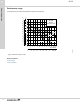
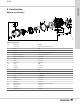
2 JP PS Construction 2. Construction Material specification 51 43 14 93 180 94 25 31 33 13 181 16a 92 21a 19 16 15 45 28 20 21 42 43 44 43 42 41 TM074225 1 26 56a 56 32 Material specification Pos. Component Material 1 Pump housing Stainless steel AISI 304 (EN 1.4301) 13 O-ring NBR 14 Motor fan Composite 15 Seal disc Stainless steel AISI 304 (EN 1.
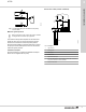
3 JP PS Installation and operation 3. Installation and operation [m] [ft] 9 Mechanical installation 8 To obtain the optimum suction capacity that the dry-installed pump is designed for, the correct dimension of the pipe system is important. If a hose is used as inlet pipe, it must be non-collapsible. The diameter of the inlet pipe must be larger than 1" if the inlet pipe is longer than 32.8 ft (10 m), or if the suction lift exceeds 13.1 ft (4 m).
3 JP PS 7 Installation and operation Suction from a well (outdoor installation) 4 3 TM058227 1 2 5 Fig. Correct pipe sizing for connection to the pump inlet or outlet 3 Maximum system pressure The maximum inlet pressure depends on the head at the actual duty point. The sum of the inlet pressure and the head must not exceed the maximum system pressure. We recommend installing a pressure-relief valve to protect the pump so that the outlet pressure does not exceed the maximum system pressure.
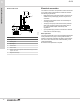
3 JP PS Electrical connection Installation and operation Suction from a tank The electrical connection and protection must be carried out in accordance with local regulations. Please also observe the following requirements: 4 1 3 2 7 • Make sure that the pump and pressure-control unit are suitable for the power supply to which they are to be connected. • The pump and pressure-control unit must always be correctly grounded.
4 JP PS Selection 4. Selection Selection guide This guide helps you size and select your pump. Follow the instructions below. Selection table Selection table for JP PS, water supply on demand. Model 1-5 taps/ 4.4-8.8 gpm/ (1-2 m3/h) JP PS 13 03 137 6-10 taps/ 13.2-17.6 gpm/ 11-20 taps/ 17.
5 JP PS Performance curves 5. Performance curves How to read the curve charts H [m] H [ft] 55 180 50 3 45 40 35 60 Hz ISO 9906:2012 3B 160 140 1 120 30 100 25 80 20 JP PS 22 10 157 60 15 40 5 20 0 0 2 0 2 4 6 0.0 0.5 1.0 1.5 8 2.0 10 12 2.5 14 3.0 16 3.5 18 4.0 20 22 24 Q [US GPM] 4.5 Q [m³/h] 4 TM074024 10 Pos.
5 JP PS 40 130 30 25 20 15 10 5 0 JP PS 13 03 137 60 Hz ISO 9906:2012 3B 120 110 90 80 70 50 20 0 0.0 180 50 160 45 40 35 80 0 0 2 4 6 0.5 1.0 8 1.5 10 2.0 12 110 25 5 10 90 70 60 50 40 30 20 10 0 14 16 Q [US GPM] 2.5 3.0 Q [m³/h] JP PS 18 07 177 60 Hz H [m] H [ft] 55 180 50 ISO 9906:2012 3B 45 140 40 120 35 100 25 80 25 80 15 40 5 20 0 0 10 0 2 4 0.0 0.5 1.0 6 1.5 8 10 2.0 12 2.5 14 3.0 16 18 20 Q [US GPM] 3.
6 JP PS Technical data 6. Technical data Operating conditions Dimensions and weights System pressure Max. 87 psi (6 bar / 0.60 MPa) Suction lift Max. 26.25 ft (8 m), including inlet-pipe pressure loss at a liquid temperature of 68 °F (20 °C) Liquid temperature Max. 104 °F (40 °C) (S1) / 140 °F (60 °C) (S3*) A TM074268 H1 H2 H C B D JP PS 13 03 137 and JP PS 18 05 154 Relative humidity Max.
6 JP PS Model JP PS 13 03 137 JP PS 18 05 154 JP PS 18 07 177 JP PS 22 10 157 Voltage [V] P1 [Hp (W)] P2 [Hp (W)] n [rpm] In [A] Istart [A] 1 x 230 1 (700) 0.6 (447) 3400 3.1 11.26 1 x 115 1 (730) 0.6 (447) 3400 6.6 22.35 1 x 230 1.2 (880) 0.8 (597) 3400 3.8 12.50 1 x 115 1.2 (900) 0.8 (596) 3400 8.0 26.30 1 x 230 1.5 (1100) 1 (746) 3400 5.1 23.70 1 x 115 1.5 (1100) 1 (746) 3400 9.7 47.54 1 x 230 2 (1450) 1.4 (1014) 3400 6.6 38.22 1 x 115 2 (1470) 1.
7 JP PS Grundfos Product Center 7. Grundfos Product Center Online search and sizing tool to help you make the right choice. https://product-selection.grundfos.com 1 2 3 4 1 2 3 4 TM070462 TM072384 All the information you need in one place Performance curves, technical specifications, pictures, dimensional drawings, motor curves, wiring diagrams, spare parts, service kits, 3D drawings, documents, system parts.
GRUNDFOS Pumps Corporation 9300 Loiret Boulevard Lenexa, Kansas 66219 USA Tel.: +1 913 227 3400 Fax: +1 913 227 3500 GRUNDFOS Water Utility Inc. 3905 Enterprise Court P.O. Box 6620 Aurora, IL 60598-0620 Phone: +1-630-236-5500 Fax: +1-630-236-5511 GRUNDFOS CBS Inc. 902 Koomey Road Brookshire, TX 77423 USA Phone: 281-994-2700 Toll Free: 1-800-955-5847 Fax: 1-800-945-4777 Peerless Pump 2005 Dr. Martin Luther King Jr US-46202 Indianapolis, Indiana U.S.A. Phone:317-925-9661 Canada GRUNDFOS Canada Inc.
ECM: 1256953 99599466 0419 Trademarks displayed in this material, including but not limited to Grundfos, the Grundfos logo and “be think innovate” are registered trademarks owned by The Grundfos Group. All rights reserved. © 2019 Grundfos Holding A/S, all rights reserved.