
Submittal Sheet

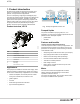
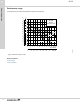

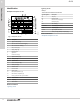

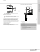
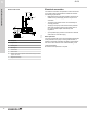
Table Of Contents

3. Installation and operation
Mechanical installation
Placing the pump above ground is generally a convenient
way to establish a water or rainwater supply. The pump can
be installed both indoors and outdoors in a well ventilated
location. When installed outdoors, the product needs a
suitable cover to protect it from exposure to direct sunlight,
rain, snow and frost. Place the product as close to the liquid
to be pumped as possible to minimize the length of the inlet
pipe. For ease of access we recommend a clearance of 20
in (0.5 m) on three sides which should include the rear side
for cooling of the motor. Fasten the product to a solid
horizontal foundation with a maximum inclination angle of ±
5 °. The base plate must be facing downwards. If the pump
is used for pumping rainwater or well water, we recommend
installing a filter on the inlet side to protect the pump from
sand, gravel or other debris. If the pump is installed above
the liquid level, we recommend that you fit a foot valve with
a strainer to the inlet pipe.
Pipe system
To obtain the optimum suction capacity that the dry-installed
pump is designed for, the correct dimension of the pipe
system is important. If a hose is used as inlet pipe, it must
be non-collapsible. The diameter of the inlet pipe must be
larger than 1" if the inlet pipe is longer than 32.8 ft (10 m), or
if the suction lift exceeds 13.1 ft (4 m).
To ensure optimum operation and longer life of the pump, a
pressure tank with a properly set air charge should be
installed in the system. See the tank manufacturer's
instructions for proper tank size selection and specific
setting of the air charge. See table below for general
guidelines.
Pressure switch
cut-on pressure
[psi]
Tank air pre-charge
(no water pressure)
[psi]
20 18
30 28
40 38
Inlet-pipe length and suction lift
The length of the inlet pipe of self-priming pumps depends
on the geodetic suction lift. The recommended maximum
length of the inlet pipe according to the suction lift is shown
in the figure below. The example shows that if the suction lift
is 8.2 ft (2.5 m), the length of the inlet pipe must not exceed
82 ft (25 m).
0
1
2
3
4
5
6
7
8
9
[m]
0
5
10
15
20
25
30
[ft]
4 8 12 16 20 24 28 32 36 40
[m]
[ft]
0 20 40 60 80 100 120
Fig.
Maximum inlet-pipe length (horizontal axis)
according to the suction lift (vertical axis)
Inlet and outlet pipes
The following are general considerations when connecting
the inlet and outlet pipes:
• Install the pipes so that air pockets are avoided,
especially on the inlet side of the pump.
• Use eccentric reducers with the tapered side down.
• Make sure the pipes are as straight as possible to avoid
unnecessary bends and fittings. We recommend long-
radius 90 ° pipe bends to decrease friction loss.
• Run the inlet pipe as direct as possible and, ideally,
make sure the length is at least ten times the pipe
diameter.
• If possible, run a horizontal inlet line. We recommend a
gradual upward slope to pumps operating in suction-lift
conditions, and a gradual downward slope to pumps
operating in positive inlet-pressure conditions.
• A short pipe must be the same diameter as the inlet
port or larger.
• A long pipe must be one or two sizes larger than the
inlet port, depending on the length.
TM040338
Fig. Recommended pipe installation to avoid friction
and air pockets
JP PS
3
8
Installation and operation