
Network Card Service Manual


CUC 7350
Schaltungsbeschreibung / Circuit Description
GRUNDIG Service 2 - 5
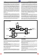
Wave filter F32005. The signal formed by the Surface Acoustic Wave
filter is applied symmetrically to Pins 48 and 49 of the signal processor.
CCVS signal demodulation is carried out in a PLL demodulator. This
PLL demodulator offers high-quality demodulation without producing
any interferences so that a quasi-parallel sound is not necessary for
inland TV sets.The required oscillator circuit F33025, CR33025 and
CC 33025 is connected to IC34015-(3),-(4). The demodulated signal
passes through an amplifier and is then present at IC34015-(6). On the
BB line, the CCVS signal arrives at a transistor which is followed by a
filter for suppressing the sound difference frequency. The CCVS
TER
lead takes the CCVS signal to IC34015-(13).The IC identifies the
synchronising signal internally and for this reason, feedback of the line
flyback pulse for gating purposes is not necessary. Corresponding to
the synchronising level a control voltage is generated. This control
voltage first acts on the controlled input amplifier of the IF. From Pin 54
the reference voltage U
τ
is applied to tuner contact 2. The AFC
information is passed through the I
2
C-bus to the processor.
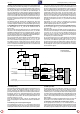
Multi-standard TV models:
The IF spectrum of frequencies is fed through a symmetrical path from
the tuner Pins 9 and 10 to the IF amplifier module Pins 11 and 12. The
signal is demodulated in IC2230. The demodulated signal passes
through an amplifier and is then present a IC2230-(10). On Pin 10 of
the module, the control voltage U
τ
is available which is applied to tuner
contact 2. In the demodulator, the d.c. voltage for the AFC is produced.
On Pin 4 of the IF module, the AFC is available. When the received
frequency increases the control voltage for AFC decreases. The
processor IC80000 evaluates the signal and fine-tunes the tuner.
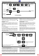
3.3 CCVS Signal
Inland TV models:
The demodulated CCVS signal leaves IC34015-(6), TDA 8374, as a
baseband signal together with the sound-IF. On the following path via
CR32027, CT32025, and the filter F32021, the CCVS signal is sepa-
rated from the sound signal and arrives at IC34015-(13).
Multi-standard TV models:
The demodulated CCVS signal is fed out of the IF module on Pin 7 and
is passed on to IC34015-(13).
At the same time, in all TV versions, the CCVS signal is routed through
CT32014, CR32016 and CR43023 to the Scart socket Pin 19. From
IC34015-(38) the signal passes through transistor CT34001 and
arrives at the teletext decoder IC46000-(8) as CCVS
TXT
signal, and in
multi-standard TVs, it is also fed to the Secam-IC34005.
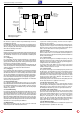
3.4 External CCVS Signal
The external CCVS signal from the Cinch socket is available at
IC34015-(17). On Pin 11, the CCVS signal from the Scart socket is
present on VHS playback, and on Pin 10 the chroma signal on S-VHS
playback is present.
des Signalprozessors. Die Demodulation des ZF-Signals erfolgt in
einem PLL-Demodulator. Dieser PLL-Demodulator bietet eine sehr
hochwertige Demodulation ohne Störprodukte, so daß im Inlandsgerät
auf einen Quasi-Parallelton verzichtet werden kann. Der dafür benö-
tigte Oszillatorkreis F33025, CR33025 und CC 33025 liegt an IC34015-
(3),-(4). Das demodulierte Signal durchläuft einen Verstärker und steht
an IC34015-(6). Über die Leitung BB gelangt das FBAS-Signal zu
einem Transistor, dem ein Filter zur Unterdrückung der Ton-Differenz-
frequenz folgt. Die Leitung FBAS
TER
führt das FBAS-Signal zum
IC34015-(13). Der IC erkennt intern das Synchronsignal ohne
Auftastung durch den Zeilenrückschlagimpuls. In Abhängigkeit des
Synchronpegels wird eine Regelspannung erzeugt. Diese Regel-
spannung wirkt zunächst auf den geregelten Eingangsverstärker der
ZF. Von Pin 54 gelangt die Regelspannung U
τ
an den Tunerkontakt 2.
Die AFC-Informationen werden über den I
2
C-Bus an den Prozessor
gegeben.
Multinormgeräte:
Die ZF kommt symmetrisch vom Tuner Pin 9 und 10 zum ZF-
Verstärker-Modul Pin 11 und 12. Die Demodulation erfolgt im IC2230.
Das demodulierte Signal durchläuft einen Verstärker und steht an
IC2230-(10). An Pin 10 des Moduls steht die Regelspannung U
τ
zur
Verfügung, die an Tunerkontakt 2 geführt wird. Im Demodulator wird
die Gleichspannung für die AFC gewonnen. Am Pin 4 des ZF-Moduls
steht die AFC zur Verfügung. Steigt die empfangene Frequenz, so
sinkt die Regelspannung für die AFC. Der Prozessor IC80000 wertet
dieses Signal aus und zieht den Tuner über Finetuning nach.
3.3 FBAS Signal
Inlandgeräte:
Das demodulierte FBAS Signal verläßt den IC34015-(6), TDA 8374 als
Basisband noch gemeinsam mit der Ton ZF. Das FBAS Signal wird im
weiteren Verlauf über CR32027, CT32025 und dem nachfolgenden
Filter F32021 vom Tonsignal befreit und gelangt zum IC34015-(13).
Multinormgeräte:
Das demodulierte FBAS-Signal verläßt das ZF-Modul an Pin 7 und
wird zu IC34015-(13) geleitet.
Gleichzeitig läuft bei allen Geräteversionen das FBAS-Signal über
CT32014, CR32016 und CR43023 zur Scart-Buchse Pin 19. Vom
IC34015-(38) und über Transistor CT34001 gelangt das Signal als
FBAS
TXT
zum Videotext-Decoder IC46000-(8), sowie bei Multinorm-
Geräten zum Secam-IC34005.
3.4 Externes FBAS-Signal
Am IC34015-(17) steht das externe FBAS-Signal von der Cinch-
Buchse. An Pin 11 steht das FBAS-Signal der Scart-Buchse bei VHS-
Wiedergabe und an Pin 10 das Chroma-Signal bei SVHS-Wiederga-
be.
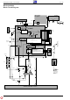
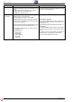
Bild ZF und Demodulation
Vision IF and Demodulation
FBAS und Ton
Ausgang
CCVS and Sound
Output
F33025
ZF vom Tuner
IF from Tuner
U
für denTuner
for the Tuner
TDA8374
~
48
49
4
54
6
~
3