2000 Autoflow Series 2000 Autoflow Fan/Heater Control Installation Instructions MODEL # 2TF - __ __ - __ __ __ MODEL # 2TFC- __ __ __ __ __ MODEL # 2TAF - __ __ __ __ Installation Manual PNEG-673 11
000 Autoflow This equipment shall be installed in accordance iwth the current INSTALLATION CODES FOR GAS BURNING APPLICANCES AND EQUIPMENT, CAN1_B149.1 and B149.2, or applicable provincial regulations which should be carefully followed in all cases. Authorities having jurisdiction shuld be consulted before installations are made.
2000 Autoflow TABLE OF CONTENTS Roof Warning, Operation & Safety................................................................................4 Safety Alert Decals.......................................................................................................5 Safety Precautions........................................................................................................6 Safety Sign-off Sheet...............................................................................................
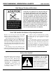
ROOF WARNING, OPERATION & SAFETY 2000 Autoflow Roof Damage Warning and Disclaimer GSI DOES NOT WARRANT ANY ROOF DAMAGE CAUSED BY EXCESSIVE VACUUM OR INTERNAL PRESSURE FROM FANS OR OTHER AIR MOVING SYSTEMS. ADEQUATE VENTILATION AND/OR "MAKEUP AIR" DEVICES SHOULD BE PROVIDED FOR ALL POWERED AIR HANDLING SYSTEMS. GSI DOES NOT RECOMMEND THE USE OF DOWNWARD FLOW SYSTEMS (SUCTION). SEVERE ROOF DAMAGE CAN RESULT FROM ANY BLOCKAGE OF AIR PASSAGES.
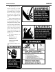
2000 Autoflow SAFETY The GSI Group, Inc. recommends contacting your local power company, and having a representative survey your installation so the wiring is compatible with their system, and adequate power is supplied to your unit. Safety decals should be read and understood by all people in the grain handling area. The rotating blade, fire warning decals and voltage danger decal must be displayed on the fan can.
SAFETY PRECAUTIONS READ THESE INSTRUCTIONS BEFORE OPERATION AND SERVICE SAVE FOR FUTURE REFERENCE 1. Read and understand the operating manual before trying to operate the dryer. 2. 3. 4. 5. 6. 2000 Autoflow Use Caution in the Operation of this Equipment The design and manufacture of this Power supply should be OFF for service of electrical components. Use dryer is directed toward operator CAUTION in checking voltage or other procedures requiring power to safety.
2000 Autoflow Date SAFETY SIGN-OFF SHEET Employer’s Signature Employee ________________________________________________________________________________________________________________________ _________________________________________________________________________________________________________________________ ________________________________________________________________________________________________________________ _________________________________________________________________________________
INSTALLATION 2000 Autoflow Fan and Heater Mounting 1. Inspect the fan platform for proper installation per instructions in the Top Dry erection manual. 2. Raise the Top Dry fan and heater units to the Top Dry Bin Eave Height Number Eave of Rings Height 5 18-5 6 22-1 7 25-9 8 29-5 9 33-1 10 36-9 11 40-5 plat form. Use the table to the right to determine the height of the platform from the base of the TopDry unit. 3.
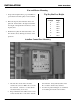
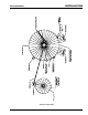
INSTALLATION 2000 Autoflow Component Placement 9
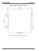
INSTALLATION Series 2000 Autoflow Control Box Bolt Pattern Figure 1: Illustration of the bolt pattern for the Autoflow control box.
CONTROL BOX MOUNTING 2000 Autoflow Fill System Control Box Mounting 1) The Fill System control Box should be mounted at eye-level. Make sure to install the Fill System Control Box so that the Fill System(s) and Aeration fan are in view.
CONTROL BOX MOUNTING Fill System Control Box Mounting Figure 2: Fill System Control Box Bolt Pattern 12 2000 Autoflow
CONTROL BOX MOUNTING 2000 Autoflow Actuator Control Box Mounting 1) Mark the third sidewall ring from the ground to indicate the cable path if dump chutes and cable are already installed. 2) Make sure that all dump chutes and chains are EVENLY adjusted so that when one chute is level the others are level as well.
CONTROL BOX MOUNTING Actuator Control Box Mounting Figure 3: Bolt pattern to drill holes for the Actuator Control Box 14 2000 Autoflow
INSTALLATION 2000 Autoflow Multi-Grain Temperature Sensor 1. Remove the two wires attached to the grain tem- perature sensor connected to terminal #22 and terminal #23 in the fan control box. 2. Mount the four grain temperature sensor brackets evenly around the drying chamber on out side leveling band posts (figure 5). band post, and across the top leveling band. 5. Take the cords through the space between the roof and the top sidewall sheet.
INSTALLATION 2000 Autoflow Grain Temperature Sensor Mounted to Leveling Band Post Figure 5: Illustration of grain temperature sensor mounted on outside leveling band post.
2000 Autoflow INSTALLATION Close-Up Detail of Grain Temperture Sensor Wiring 17
INSTALLATION 2000 Autoflow Plenum Temperature Sensor The plenum temperature sensor is the small grey PVC junction box attached by a cord to the fan/heater control box on the master fan/heater unit. 1. On either side of the fan/heater, drill one 3/4” hole even with the fan/heater unit in a valley on the bin sidewall. 2. Insert the probe through the 3/4” hole. 3. Position the housing so the cord exits the housing horizontally, and the tabs fall on the sidewall peaks. 4.
INSTALLATION 2000 Autoflow Airswitch 1. On either side of the master fan/ heater, drill one 3/4” hole even with the fan/heater unit in a valley on the bin sidewall. 2. Insert the airswitch probe through the 3/4” hole. 3. Position the housing so the cord exits the housing horizontally, and the vents open downward. 4. Use four self drilling screws to mount the housing to the bin sidewall. Airswitch mounted on the bin sidewall. 5. Caulk between the housing and the sidewall to seal.
INSTALLATION 2000 Autoflow Fan/heater unit mounted to the bin, showing the plenum high limit, the airswitch, and cord going through the eave to the grain temperature sensor brackets.
INSTALLATION 2000 Autoflow Wet Supply Rotary Switch 1) Drill a 2” diameter hole through the hopper bottom. If a flat bottom bin is being used for a wet storage tank the Wet Supply Rotary Switch would be mounted 45 degrees up the sidewall from the center of the bin. Example: If the wet storage bin is 18’ in diameter then the Wet Supply Rotary Switch would be mounted 9’ up the sidewall. 5) Add foam weather strip around the top and side of the mounting plate. 2) If the bin is 2.
INSTALLATION 2000 Autoflow Figure 6 22
INSTALLATION 2000 Autoflow Storage Chamber High Limit Rotary Switch Installation 1) Drill a 2” diameter hole through the sidewall 3’ below the fan/heater. 2) If the bin is 2.66” corrugation the hole should be centered on an outside hill. 3) If the bin is 4.00” corrugation the hole should be centered on an outside valley. 4) Use the mounting plate as a pattern and drill four 3/8” holes through the sidewall at the switch location so the plate can be bolted to the bin.
INSTALLATION 2000 Autoflow Figure 7 24
2000 Autoflow The three (3) Drying Chamber Rotary Switches are used by the series 2000 Autoflow to monitor the location of grain in the Drying Chamber. The rotary switch with the shortest shaft extension is the Drying Chamber Overflow Rotary Switch. It is used as a safety in the event the Chamber High Level Rotary Switch fails. The rotary switch with the longest extension is the Drying Chamber Low Level Rotary Switch.
INSTALLATION 2000 Autoflow Drying Chamber Low-Level Rotary Switch Installation 1) Drill a 2” diameter hole through the roof panel at the location shown in figure 8. See component placement on page 9 for proper placement in relation to fill auger. right angles with the roof panel ribs or facing towards the eave. 6) Caulk the underside of the mounting plate and on all sides of the 2” hole. 7) Bolt the assembly to the roof panel.
INSTALLATION 2000 Autoflow Figure 9 27
INSTALLATION 2000 Autoflow Drying Chamber High-Level Rotary Switch Installation 1) Drill a 2” diameter hole through the roof panel at the location shown in figure 8. See Component placement on page 9 for proper placement in relation to fill auger. right angles with the roof panel ribs or facing towards the eave. 6) Caulk the underside of the mounting plate and on all sides of the 2” hole. 7) Bolt the assembly to the roof panel.
INSTALLATION 2000 Autoflow Figure 10 29
INSTALLATION 2000 Autoflow Drying Chamber Overflow Rotary Switch Installation 1) Drill a 2” diameter hole through the roof panel at the location shown in figure 8. See Component placement ` on page 9 for proper placement in relation to fill auger. included) to the rotary switch power pak threads and thread the rotary switch power pack into the mounting plate coupling. 5) Make sure that the conduit hole is at right angles with the roof panel ribs or facing towards the eave.
INSTALLATION 2000 Autoflow Figure 11 31
INSTALLATION 2000 Autoflow Liquid Propane (LP) Top Dry dryers have internal vaporizers, and they are designed to operate on liquid draw from the supply tank. Avoid using propane supply tanks that have been used for vapor draw for long periods of time. When using liquid draw systems any moisture that may be present in tanks or lines may freeze when the system is used in cold weather. To avoid this situation, purge the system with methanol.
INSTALLATION 2000 Autoflow Natural Gas (NG) This dryer is designed to operate on natural gas. Natural gas units have a larger orifice to accommodate lower pressures sometimes found with natural gas and do not have vaporizer coils like liquid propane units. A regulated pressure of 10 PSI minimum, 30 PSI maximum must be provided at the field connection point on the fan and heater unit, with gas available in sufficient volume to maintain the operating pressure.
ELECTRICAL POWER SUPPLY 2000 Autoflow Conduit Runs Control Wires Run #1 Autoflow Control Box to Master Fan/Heater Control Box Five (5)-Control wires 16ga minimum (NOTE: A shielded two conductor 16ga cable should be used for the network connections.
2000 Autoflow ELECTRICAL POWER SUPPLY Power Supply An adequate power supply and proper wiring are important factors for maximum performance and long life of the dryer. Electrical service must be adequate enough to prevent low voltage damage to motors and control circuits (see Electrical Load Information on page 40). In 220V 1 ph and 220V 3 ph systems a separate neutral wire is required for the 120V heater circuit, and should be connected to terminal #1 in the master heater.
ELECTRICAL POWER SUPPLY 12345678901234567890123456789012123456789012345678901234567890121234567 12345678901234567890123456789012123456789012345678901234567890121234567 12345678901234567890123456789012123456789012345678901234567890121234567 12345678901234567890123456789012123456789012345678901234567890121234567 12345678901234567890123456789012123456789012345678901234567890121234567 12345678901234567890123456789012123456789012345678901234567890121234567 1234567890123456789012345678901212345678901234567890123
POWER/MOTOR WIRING 2000 Autoflow The Following diagram details the configuration for correct main power installation. Use the diagram in conjunction with the Electrical Load information and Wire Size information provided. The diagram details the correct main power installation for 220V 1 ph, 230V ph, 460V 3ph, 575V 3ph, and 380V 50hz power supplies. On all three phase systems put the leg with the NOTE: Standard electrical safety should be used.
ELECTRICAL POWER SUPPLY Electrical Load Information The following charts provide information for the electrician wiring the grain dryer, and are a reference guide for parts. It is recommended that you contact your local power company and have a representatives survey the installation to see that your wiring is compatible with their system and that adequate power is supplied to your unit. Remember that the only thing connected to the recommended service amps should be your grain dryer.
ELECTRICAL POWER SUPPLY 2000 Autoflow Wire Size Information Dryer Fan Size 36" 36" 42" 42" 42" 42" Voltage Copper Aluminium Copper Aluminium Copper Aluminium Horsepower 100' Run 100' Run 200' Run 200' Run 300' Run 300' Run 220v1ph 10-12 6 4 4 2 2 0 208v3ph 10-12 6 4 4 2 3 2 220v3ph 10-12 6 4 4 2 3 2 380v50hz 10-12 10 8 8 6 6 4 460v3ph 10-12 10 8 8 6 6 4 575v3ph 10-12 10 8 8 6 6 4 220v1ph 10-16 4 2 2 0 1 00 208v3ph 15 6 4 4 2 2 0 220v
ELECTRICAL POWER SUPPLY 2000 Autoflow Fill System Control Box Electrical Load Information The following charts provide information for the electrician wiring the grain dryer, and are a reference guide for parts. It is recommended that you contact your local power company and have a representative survey the installation to see that your wiring is compatible with their system and that adequate power is supplied to your unit.
2000 Autoflow ELECTRICAL POWER SUPPLY Figure 18 41
ELECTRICAL POWER SUPPLY 2000 Autoflow Autoflow to Master Fan/Heater Unit Interconnect The Master Fan/Heater Unit is the only fan and heater in a single fan unit. In two fan units it is the fan/heater with the airswitch, plenum temperature sensor, and grain temperature sensor connected to it. DO NOT run the control wires for the Master Fan/Heater in the same conduit as the power wires for the fan motor. To wire the Master Fan/Heater Unit to the Autoflow Control Box do the following.
ELECTRICAL POWER SUPPLY 2000 Autoflow Autoflow to Actuator Interconnect The Actuator Control Box houses the 24V DC linear actuator, two (2) 12V DC Batteries, and a 24V DC battery charger. The linear actuator raises and lowers the dump chutes to unload grain automatically from the drying chamber to the storage chamber. The two (2) 12V DC batteries act as a backup to prevent wet grain from dumping into the storage chamber during a power outage.
ELECTRICAL POWER SUPPLY 2000 Autoflow Autoflow to Wet Supply Rotary Switch Interconnect The 110V AC rotary switch located in the wet storage tank is used to inform the computer on the availability of wet grain. The Wet Supply Rotary Switch use 110V AC to power the motor and 12V DC + to switch a signal back to the computer. To wire the Wet Supply Rotary Switch to the Autoflow Control Box do the following: 1) Run Four (4) control wires from the Autoflow Control Box to the Wet Supply Rotary Switch.
2000 Autoflow ELECTRICAL POWER SUPPLY Autoflow to Storage Chamber Rotary Switch Inerconnect The 110V AC Rotary switch located in the storage tank is used to inform the computer on the availability of wet grain. The Storage Chamber Rotary Switch is mounted three (3) feet below the fan/heater unit(s). The Storage Chamber Rotary Switch use 110V AC to power the motor and 12V DC + to switch a signal back to the computer.
ELECTRIAL POWER SUPPLY 2000 Autoflow Autoflow to Drying Chamber Rotary Switches Interconnect The three (3) 110V AC rotary switches located in the drying chamber are used to inform the computer on the location of grain in the drying chamber. The rotary switch with the shortest extension is the Drying Chamber Overflow Rotary Switch. It is used as a safety in the event the Chamber High Level Rotary Switch fails. The rotary switch with the longest extension is the Drying Chamber Low Level Rotary Switch.
ELECTRIAL POWER SUPPLY 2000 Autoflow Figure 23 47
ELECTRICAL POWER SUPPLY 2000 Autoflow Autoflow to Fill System Control Box Interconnect The Fill System Control Box houses the starter (s) for the fill system(s) that load grain into the Top Dry Autoflow Unit and for the aeration fan. DO NOT run the control wires for the Fill System Control Box in the same conduit used for the power wires for the fill system and aeration fan motors. To wire the Fill System Control to the Autoflow Control Box do the following.
2000 Autoflow ELECTRICAL POWER SUPPLY Autoflow to Ground Interconnect Figure 25 49
ELECTRICAL POWER SUPPLY 2000 Autoflow Master to Slave Interconnect A slave fan/heater unit can be added to operate in unison with the master fan/heater unit. The interconnect between the master and slave fan/heater units remains the same regardless of the type or presence of a control center. To wire a slave fan/heater unit to a master fan/ heater unit do the following: NOTE: Do NOT use solid wire for interconnection. NOTE: A shielded 16 gauge cable is recommended for use on the network connections.
ELECTRICAL POWER SUPPLY 2000 Autoflow Slave to Slave Interconnect A second slave fan/heater unit can be added to operate in unison with the master fan/heater unit and another slave fan/heater unit. This would create a three fan unit. The interconnect between the first slave fan/heater unit and the second slave fan/heater unit remains the same regardless of the type or presence of a control center.
ELECTRICAL POWER SUPPLY 2000 Autoflow Battery Hook-Up Two (2) lawn and garden type 12V DC Batteries are required for proper operation of the Actuator Control Box. The two (2) 12V DC batteries are wired in series to provide the 24V DC linear actuator with the voltage required to operate. The two (2) 12V DC batteries should be mounted on the shelves provided in the Actuator Control Box. terminal on one battery to the positive terminal on the other battery.
ELECTRICAL POWER SUPPLY 2000 Autoflow Dump Chute Cable Installation After complete installation of the Autoflow Unit the cable should be hooked up to the linear actuator in the Actuator Control Box. To test the linear actuator and install the cable do the following: 1) Turn all switches on the Autoflow control front panel to the “off” position. 7) Place the Dump switch in the “auto” position and press the Stop switch. 8) The linear actuator should retract and stop.
ELECTRICAL POWER SUPPLY Figure 29 54 2000 Autoflow
2000 < Autoflow cr> WARRANTY THE GSI GROUP, INC. ("GSI") WARRANTS ALL PRODUCTS MANUFACTURED BY GSI TO BE FREE OF DEFECTS IN MATERIAL AND WORKMANSHIP UNDER NORMAL USAGE AND CONDITIONS FOR A PERIOD OF TWELVE MONTHS AFTER RETAIL SALE TO THE ORIGINAL END USER OF SUCH PRODUCTS. GSI'S ONLY OBLIGATION IS, AND PURCHASER'S SOLE REMEDY SHALL BE FOR GSI, TO REPAIR OR REPLACE, AT GSI'S OPTION AND EXPENSE, PRODUCTS THAT, IN GSI'S SOLE JUDGMENT, CONTAIN A MATERIAL DEFECT DUE TO MATERIALS OR WORKMANSHIP.
2000 Autoflow Revision #1 February 1998 56
AIRSTREAM GRAIN CONDITIONING SYSTEMS 2000 Autoflow 1004 E. Illinois St.