
OPERATING INSTRUCTIONS POWER VENTED GAS FIRED WATER HEATER


-8-
Ensure that there is no movement of the clamped assembly
once it is completed.
IV) Water Pipe Connections
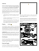
Water piping and fittings should be installed as shown in Figure
8.
1. Close main water supply and drain the piping system where
water heater is to be connected.
2. Water heater “inlet” and “outlet” are identified in the top
cover (see figure 8).
3. When attaching solder (sweat) fittings, DO NOT APPLY
HEAT DIRECTLY TO THE WATER HEATER
NIPPLES or the plastic liners will be damaged. Sweat
adapters to the first section of the water piping before
threading onto the water heater.
4. Install a manual shut-off valve in the cold water supply line.
It is good plumbing practice to include unions at the hot and
cold connections as shown. (Fig. 8)
5. IMPORTANT: Before putting the water heater into
service, make sure that a properly rated and sized
temperature and pressure relief valve is installed in the
designated fitting in the water heater. The relief pressure
marked on the relief valve must not exceed that stated on
the rating plate of the water heater.
IMPORTANT: The relief valve must be connected to a
discharge or drain pipe no smaller in size than the outlet of
the relief valve. This pipe must not be valved, plugged,
allowed to freeze, or be restricted in any way. Terminate
close to a drain of adequate capacity.
The relief valve is necessary to avoid excessive water
pressure or water temperature from developing. Such a
condition could cause serious personal injury due to scalding
or serious physical damage to the water heater. This safety
device shall be checked annually for proper operation.
Check local Codes.
6. With water piping installed, check that a hot water faucet
served by the water heater is open and that the heater drain
valve is closed. Open the cold water supply valve and fill the
water heater and piping system with water. When an
uninterrupted stream of water flows from the faucet, the
system is full. Close faucet. Check for leaks and repair as
necessary.
7. Connect a hose to the drain valve and connect to drain. Open
drain and let water run until clear to flush out any foreign
matter that may have entered the system. Once flushed,
close the drain valve and disconnect hose.
V) Gas Service
Gas piping and fitting shall be installed as shown in Figure 9.
Check that a properly sized gas meter and regulator are available
to service the water heater. If other appliances are using the
same meter and regulator, ensure that the capacity of the meter
and regulator matches that of the combined input of all
appliances connected to it. The gas control supplied with this
water heater is designed for a maximum inlet pressure of 0.5
p.s.i. (14" water column).