Digital Storage Oscilloscope GDS-2000A Series PROGRAMMING MANUAL GW INSTEK PART NO. Version 1.
October 2012 This manual contains proprietary information which is protected by copyright. All rights are reserved. No part of this manual may be photocopied, reproduced or translated to another language without prior written consent of Good Will Corporation. The information in this manual was correct at the time of printing. However, Good Will continues to improve products and reserves the right to change specifications, equipment, and maintenance procedures at any time without notice.
TABLE OF CONTENTS Table of Contents INTERFACE OVERVIEW ..................................................... 5 Front Panel Overview ................................. 5 Interface Configuration .............................. 6 COMMAND OVERVIEW .................................................. 21 COMMAND OVERVIEW .................................................. 21 Command Syntax ..................................... 21 List of Commands in Functional Order .... 23 COMMAND DETAILS ...........................
GDS-2000AA Programming Manual Time Commands .................................... Bus Decode Commands ......................... Mark Commands .................................... Search Commands ................................. Digital Commands ................................. Label Commands ................................... Utility Commands .................................. 154 155 166 168 192 199 207 APPENDX .......................................................................
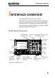
INTERFACE OVERVIEW INTERFACE OVERVIEW This manual describes how to use the GDS-2000A’s remote command functionality and lists the command details. The Overview chapter describes how to configure the GDS-2000A USB remote control interface, Ethernet interface, GPIB interface and RS-232 interface.
GDS-2000A Programming Manual Interface Configuration Configure USB Interface USB Configuration Panel Operation PC side connector Type A, host GDS-2000A side connector Type B, device Speed 1.1/2.0 (high speed) USB Class CDC (communications device class) 1. Press the Utility key. Utility 2. Press I/O from the bottom menu. 3. Press USB Device Port from the side menu and select Computer. 4. Connect the USB cable to the rear panel device port. 5.
INTERFACE OVERVIEW Configure RS-232C Interface RS-232C Configuration Panel Operation Connector DB-9, Male Baud rate 2400, 4800, 9600, 19200, 38400, 57600, 115200 Parity None, Odd, Even Data bit 8 (fixed) Stop bit 1, 2 1. Press the Utility key. Utility 2. Press I/O from the bottom menu. 3. Press RS-232C from the side menu. 4. Use the side menu to set the Baud Rate. Baud Rate 2400, 4800, 9600, 19200, 38400, 57600, 115200 5. Press Stop Bit to toggle the number of stop bits. Stop Bits 1, 2 6.
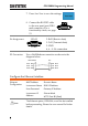
GDS-2000A Programming Manual 7. Press Save Now to save the settings. 8. Connect the RS-232C cable to the rear panel port: DB-9 male connector. For a functionality check, see page 13. Pin Assignment 12 34 5 2: RxD (Receive data) 3: TxD (Transmit data) 6 789 5: GND 4, 6 ~ 9: No connection PC Connection Use a Null Modem connection as shown in the diagram below.
INTERFACE OVERVIEW Background The Ethernet interface is used for remote configuration of the oscilloscope over a network using the integrated web server or for remote control using a socket server connection. For details, please see the Web Server Configuration section in the user manual or the Socket Server section on page 11. Panel Operation 1. Connect the Ethernet cable to the LAN port on the DS2-LAN module. 2. Press the Utility key. Utility 3. Press I/O from the bottom menu. 4.
GDS-2000A Programming Manual 6. Use the Up and Down arrows on the side menu to navigate to each Ethernet configuration item. Items MAC Address, Instrument Name, User Password, Instrument IP Address, Domain Name, DNS IP Address, Gateway IP Address, Subnet Mask Note: HTTP Port is fixed at 80. 7. Use the Variable knob to highlight a character and use the Select key to choose a character. VARIABLE Select Press Backspace to delete a character.
INTERFACE OVERVIEW Configure Socket Server The GDS-2000A supports socket server functionality for direct twoway communication with a client PC or device over LAN. By default, the Sockets Server is off. Configure Socket 1. Configure the IP address for the Server GDS-2000A. 2. Press the Utility key. Page 7 Utility 3. Press I/O from the bottom menu. 4. Press Socket Server from the side menu. 5. Press Select Port and choose the port number with the Variable knob. Range 1024~65535 6.
GDS-2000A Programming Manual Configure GPIB Note To use GPIB, the optional module, DS2-GPIB, must be installed. Please see the user manual for installation details. Connection 1. Connect a GPIB cable from a PC to the installed GPIB module. Configure GPIB 2. Press the Utility key. Utility 3. Press I/O from the bottom menu. 4. Use the Variable knob to set the GPIB Address from the side menu. This option will only be available when the GPIB module is installed.
INTERFACE OVERVIEW USB/RS-232C Functionality Check Terminal Application (USB/RS-232C) Invoke a terminal application such as RealTerm. For RS-232C and USB, set the COM port, baud rate, stop bit, data bit, and parity accordingly. To check the COM port number and associated port settings, see the Device Manager in the PC. For WinXP: Control panel → System → Hardware tab Example: Configuring RealTerm for RS232C communication. Functionality Check Key in this query command via the terminal application.
GDS-2000A Programming Manual Socket Server Functionality Check NI Measurement To test the socket server functionality, National and Automation Instruments Measurement and Automation Explorer Explorer can be used. This program is available on the NI website, www.ni.com. Operation 1. Start the NI Measurement and Automation Explorer (MAX) program. Using Windows, press: Start>All Programs>National Instruments>Measurement & Automation 2.
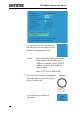
INTERFACE OVERVIEW 4. Select Auto-detect of LAN Instrument from the popup window. The GDS-2000A should be automatically detected. If the GDS-2000A is not detected, choose the manual option. 2 3 4 5. Select the IP address that corresponds to the GDS-2000A and click Next.
GDS-2000A Programming Manual 6. The GDS-2000A will now appear under Network Devices in the Configuration Panel. Functionality Check 7. Click the Open Visa Test Panel to send a remote command to the GDS-2000A. 7 6 8. Click on the viWrite tab. The *IDN? query should already be in the buffer area. 9. Click Execute to execute the query.
INTERFACE OVERVIEW 10. Click the viRead tab. 11. Click Execute to read the return parameter from the *IDN? query. 12. The manufacturer, model number, serial number and firmware version will be displayed in the buffer. For example: GW, GDS-2074A, P930116, V1.
GDS-2000A Programming Manual GPIB Functionality Check To check that the GPIB connection is working, National Instruments Measurement & Automation Explorer (MAX) can be used. The following function check is based on version 4.6.2. For further information about National Instruments, please see the NI website at www.ni.com. Operation 1. Start the NI Measurement and Automation Explorer (MAX) program. Using Windows, press: Start>All Programs>National Instruments>Measurement & Automation 2.
INTERFACE OVERVIEW 3. Press the Scan for Instruments button. 4. In the Connected Instruments panel the GDS2000A should be detected as Instrument 0 with the address the same as that configured on the GDS-2000A. 5. Double click the Instrument 0 icon. 3 2 4 5 6. Click on Communicate with Instrument. 7. In the NI-488.2 Communicator window, ensure *IND? is written in the Send String: text box. Click on the Query button to send the *IDN? query to the instrument. 8.
GDS-2000A Programming Manual 6 7 8 9. The function check is complete.
COMMAND OVERVIEW COMMAND OVERVIEW The Command overview chapter lists all GDS2000A commands in functional order as well as alphabetical order. The command syntax section shows you the basic syntax rules you have to apply when using commands. Command Syntax Compatible standard USB CDC_ACM compatible SCPI, 1994 (partially compatible) Command forms Commands and queries have two different forms, long and short.
GDS-2000A Programming Manual Command format :TIMebase:SCALe LF 1: command header 2: single space 1 2 3 4 3: parameter 4: message terminator Parameter Type Description Example boolean logic 0, 1 Integers 0, 1, 2, 3 floating point 0.1, 3.14, 8.5 floating point 4.5e-1, 8.25e+1 with an exponent any of NR1, 2, 3 Message terminator LF line feed code Note Commands are non-case sensitive. 22 1, 1.5, 4.
COMMAND OVERVIEW List of Commands in Functional Order Common *IDN? .......................................................................... 35 *LRN?.......................................................................... 35 *SAV ............................................................................ 37 *RCL ............................................................................ 38 *RST ............................................................................ 38 *CLS ......................
GDS-2000A Programming Manual Math :MATH:DISP ................................................................ 51 :MATH:TYPe ................................................................52 :MATH:DUAL:SOURce .........................................52 :MATH:DUAL:OPERator .............................................52 :MATH:DUAL:POSition ...............................................53 :MATH:DUAL:SCALe ...................................................53 :MATH:FFT:SOURce .............................
COMMAND OVERVIEW :CURSor:XY:RECTangular:Y:DELta ............................ 66 :CURSor:XY:POLar:RADIUS:POSition................. 66 :CURSor:XY:POLar:RADIUS:DELta ............................ 67 :CURSor:XY:POLar:THETA:POSition .................. 67 :CURSor:XY:POLar:THETA:DELta .............................. 67 :CURSor:XY:PRODuct:POSition .......................... 68 :CURSor:XY:PRODuct:DELta...................................... 68 :CURSor:XY:RATio:POSition ................................
GDS-2000A Programming Manual :MEASure:RPReshoot ..................................................83 :MEASure:PPULSE.......................................................84 :MEASure:NPULSE ......................................................85 :MEASure:PEDGE ........................................................85 :MEASure:NEDGE .......................................................86 :MEASure:AMPlitude ...................................................86 :MEASure:MEAN ...............................
COMMAND OVERVIEW :MEASUrement:STATIstics:WEIghting .....................105 :MEASUrement:STATIstics .......................................105 Reference :REF:DISPlay........................................................106 :REF:TIMebase:POSition ....................................106 :REF:TIMebase:SCALe ........................................107 :REF:OFFSet ........................................................107 :REF:SCALe ..........................................................
GDS-2000A Programming Manual :TRIGger:DELay:TYPe ................................................ 121 :TRIGger:DELay:TIMe ................................................ 121 :TRIGger:DELay:EVENt.............................................. 122 :TRIGger:DELay:LEVel ............................................... 122 :TRIGger:PULSEWidth:POLarity ............................... 122 :TRIGger:RUNT:POLarity .......................................... 123 :TRIGger:RUNT:WHEn .......................................
COMMAND OVERVIEW :TRIGger:BUS:B1:SPI:DATa:SIZe ..............................139 :TRIGger:BUS:B1:SPI:DATa:MISO:VALue ................139 :TRIGger:BUS:B1:SPI:DATa:MOSI:VALue ................140 :TRIGger:BUS:B1:PARallel:VALue .............................141 :TRIGger:LOGic:INPut:CLOCK:SOURce ...................141 :TRIGger:LOGic:PATtern ...........................................142 :TRIGger:LOGic:PATtern:INPut:D ......................142 :TRIGger:LOGic:PATtern:DELTatime ........................
GDS-2000A Programming Manual :BUS1:UART:TX:SOURce .......................................... 160 :BUS1:UART:RX:SOURce .......................................... 160 :BUS1:SPI:SCLK:POLARity ........................................ 161 :BUS1:SPI:SS:POLARity ............................................. 161 :BUS1:SPI:WORDSize ............................................... 161 :BUS1:SPI:BITORder ................................................. 162 :BUS1:SPI:SCLK:SOURce ........................................
COMMAND OVERVIEW :SEARCH:TRIGger:RUNT:TIMe.................................176 :SEARCH:TRIGger:RISEFall:WHEn ...........................176 :SEARCH:TRIGger:RISEFall:TIMe .............................177 :SEARCH:TRIGger:LOGic:INPut:CLOCK:SOURce ...177 :SEARCH:TRIGger:LOGic:PATtern ............................178 :SEARCH:TRIGger:LOGic:PATtern:INPut:D .............178 :SEARCH:TRIGger:LOGic:PATtern:DELTatime ........179 :SEARCH:TRIGger:LOGic:PATtern:WHEn ................179 :SEARCH:TRIGger:BUS:TYPe ............
GDS-2000A Programming Manual :DIGital:MEMory ....................................................... 197 :DIGital:LMEMory ..................................................... 198 Label Commands :CHANnel:LABel.................................................. 199 :CHANnel:LABel:DISPlay .................................... 200 :REF:LABel ........................................................... 200 :REF:LABel:DISPlay ............................................. 201 :BUS1:LABel ................
COMMAND DETAILS COMMAND DETAILS The Command details chapter shows the detailed syntax, equivalent panel operation, and example for each command. For the list of all commands, see page23. Common Commands ............................... 35 Acquisition Commands ............................ 39 Autoscale Commands .............................. 44 Vertical Commands .................................. 45 Math Commands ..................................... 51 Cursor Commands ...................................
GDS-2000A Programming Manual Digital Commands ................................. 192 Label Commands ................................... 199 Utility Commands ..................................
COMMAND DETAILS Common Commands *IDN? .......................................................................... 35 *LRN?.......................................................................... 35 *SAV ............................................................................ 37 *RCL ............................................................................ 38 *RST ............................................................................ 38 *CLS ....................................................
GDS-2000A Programming Manual CH1;ADVanced:EDIT:SOURce2 CH2;ADVanced:EDIT:OPERator PLUS;ADVanced:POSition 0.000E+00;ADVanced:SCALe ?;:MEASure:GATing SCREEN;SOURce1 CH1;SOURce2 CH2;:TIMebase:MODe MAIN;SCALe 2.000E04;POSition 0.000E+00;WINDow:SCALe 1.000E-05;:ACQuire:MODe SAMPE;AVERage 4;:CURSor:SOURce CH1;MODe ;H1Position ;H2Position ;V1Position ;V2Position ---- --- ---- ---- ;:HARDcopy:MODe SAVE;PRINTINKSaver ON;SAVEINKSaver OFF;SAVEFORMat BMP;ASSIGN IMAGE;:TRIGger:FREQuency 1.
COMMAND DETAILS 0.00V;:TRIGger:HLEVel 0.00V;:TRIGger:LLEVel 0.00V;:TRIGger:PULSEWidth:POLarity POSITIVE;:TRIGger:RUNT:POLarity POSITIVE;:TRIGger:RISEFall:SLOP RISE;:TRIGger:PULSe:WHEn THAN;:TRIGger:PULSe:TIMe 8.000e-08;:TRIGger:RUNT:WHEn THAN;:TRIGger:RUNT:TIMe 8.000e-08;:TRIGger:RISEFall:WHEn THAN;:TRIGger:RISEFall:TIMe 8.000e08;:SEARCH:TRIGGER:LOGIC:INPut:CLOCK:EDGe RISE;SOURce NONE;:SEARCH:TRIGGER:LOGIC:PATTERM:INPUT::SEARCH:TRIG GER:LOGIC:PATTERM:WHEN TRUE;:TRIGGER:LOGIC:PATTERM:DELTATIME 1.
GDS-2000A Programming Manual Example *SAV 1 Saves the current panel settings to Set 1.. *RCL Set Description Recalls a set of panel settings. Syntax *RCL {1 | 2 | 3 |…. | 20} Example *RCL 1 Recalls the selected setup from Set 1. *RST Set Description Resets the GDS-2000A (recalls the default panel settings). Syntax *RST *CLS Set Description Clears the error queue.
COMMAND DETAILS Acquisition Commands :ACQuire:AVERage...................................................... 39 :ACQuire:MODe ......................................................... 39 :ACQuire:MEMory? .............................................. 40 :ACQuire:LMEMory? .............................................41 :ACQuire:STATe?...................................................41 :ACQuire:INTERpolation ............................................ 42 :ACQuire:FILTer ...........................
GDS-2000A Programming Manual Related Commands :ACQuire:AVERage Parameter SAMPle Sample mode sampling PDETect Peak detect sampling AVERage Average sampling mode Example :ACQuire:MODe PDETect Sets the sampling mode to peak detection. :ACQuire:MEMory? Query Description Returns the data in acquisition memory for the selected channel as a header + raw data.
COMMAND DETAILS :ACQuire:LMEMory? Query Description Returns the data in acquisition memory for the selected channel as a header + raw data. This is the equivalent to the Detail LM format. Syntax :ACQuire:LMEMory? Related Commands :ACQuire:RECOrdlength Parameter Example :ACQuire1:LMEMory? :HEADer Channel number (1 to 4) Format,2.0A,Memory Length,1000000,IntpDistance,0,Trigger Address,2499,Trigger Level,9.
GDS-2000A Programming Manual Example :ACQuire1:STATe? 0 Returns 0. The channel 1’s raw data is not ready. Note: If the oscilloscope changes the acquisition status from STOP to RUN, the status will be reset as zero. Set :ACQuire:INTERpolation Query Description Selects or returns the interpolation mode. Syntax :ACQuire:INTERpolation {ET | SINC | ?} Parameter/Return ET parameter SINC Example Set the Equivalent Time interpolation.
COMMAND DETAILS parameter SHORT Example :ACQuire:RECOrdlength? Short record length. AUTO The record length is currently set to AUTO. Set :HEADer Query Description Configures whether the :ACQuire:MEM or :ACQuire:LMEM return data will contain header information or not. It is set to ON by default. Syntax :HEADer {OFF | ON | ?} Related Commands :ACQuire:MEMory? :ACQuire:LMEMory? Parameter Channel number (1 to 4) ON Add header information. OFF Don’t add header information.
GDS-2000A Programming Manual Autoscale Commands :AUTOSet .....................................................................44 :AUTORSET:MODe .....................................................44 :AUTOSet Set Description Runs the Autoset function to automatically configure the horizontal scale, vertical scale, and trigger according to the input signal. Syntax :AUTOSet Set :AUTORSET:MODe Query Description Sets the Autoset mode or queries its state.
COMMAND DETAILS Vertical Commands :CHANnel:BWLimit .............................................. 45 :CHANnel:COUPling............................................ 46 :CHANnel:DESKew .............................................. 46 :CHANnel:DISPlay ............................................... 46 :CHANnel:EXPand ............................................... 47 :CHANnel:IMPedance? ........................................ 47 :CHANnel:INVert ...........................................
GDS-2000A Programming Manual Set :CHANnel:COUPling Query Description Selects or returns the coupling mode. Syntax CHANnel:COUPling {AC | DC | GND | ?} Parameter Channel 1,2,3,4 AC AC coupling DC DC coupling GND Ground coupling Return parameter Returns the coupling mode. Example :CHANnel1:COUPling DC Sets the coupling to DC for Channel 1. Set :CHANnel:DESKew Query Description Sets the deskew time in seconds.
COMMAND DETAILS Return Parameter ON Channel is on. OFF Channel is off Example :CHANnel1:DISPlay ON Turns on Channel 1 Set :CHANnel:EXPand Query Description Sets Expand By Ground or Expand By Center for a channel or queries its status. Syntax :CHANnel:EXPand {GND | CENTer | ?} Parameter Channel 1,2,3,4 GND Ground CENTer Center Return parameter GND Expand By Ground CENTER Expand By Center Example :CHANnel1:EXPand GND Sets Channel 1 to Expand By Ground.
GDS-2000A Programming Manual Set :CHANnel:INVert Query Description Inverts a channel or returns its status. Syntax :CHANnel:INVert {OFF | ON | ?} Parameter Channel 1, 2, 3, 4 OFF Invert off ON Invert on Return parameter ON Invert on OFF Invert off Example :CHANnel1:INVert ON Inverts Channel 1 Set :CHANnel:POSition Query Description Sets or returns the position level for a channel. Note The vertical position will only be set to closest allowed value.
COMMAND DETAILS Set :CHANnel:PROBe:RATio Query Description Sets or returns the probe attenuation factor. Syntax :CHANnel:PROBe:RATio { | ?} Related Commands :CHANnel:PROBe:TYPe Parameter Channel 1, 2, 3, 4 Probe attenuation factor. Return parameter Returns the probe factor. Example :CHANnel1:PROBe:RATio 1.00E+0 Sets the Channel 1 probe attenuation factor to 1x Set :CHANnel:PROBe:TYPe Query Description Sets or returns the probe type (voltage/current).
GDS-2000A Programming Manual Syntax :CHANnel:SCALe { | ?} Parameter Channel 1, 2, 3, 4 Vertical scale: 2e–3 to 1e+1 2mV to 10V (Probe x1) Return parameter Returns the vertical scale in volts or amps. Example :CHANnel1:SCAle 2.
COMMAND DETAILS Math Commands :MATH:DISP ................................................................51 :MATH:TYPe ............................................................... 52 :MATH:DUAL:SOURce ........................................ 52 :MATH:DUAL:OPERator ............................................ 52 :MATH:DUAL:POSition .............................................. 53 :MATH:DUAL:SCALe .................................................. 53 :MATH:FFT:SOURce ..................................
GDS-2000A Programming Manual Set :MATH:TYPe Query Description Queries or sets the Math type to FFT, Advanced Math or to dual channel math operations Syntax :MATH:TYPe { DUAL | ADVanced | FFT | ? } Related Commands :MATH:DISP Parameter DUAL Dual channel operations ADVanced Advanced math operations FFT FFT operations Return parameter Returns the math type. Example :MATH:TYPe DUAL Sets the Math type to dual channel math operation.
COMMAND DETAILS Syntax :MATH:DUAL:OPERator {PLUS | MINUS | MUL| DIV|?} Parameter PLUS + operator MINUS - operator MUL operator DIV ÷ operator Return parameter Returns operator type. Example :MATH:DUAL:OPERator PLUS Sets the math operator as plus (+). Set :MATH:DUAL:POSition Query Description Sets the vertical position of the displayed math result expressed by division.
GDS-2000A Programming Manual Set :MATH:FFT:SOURce Query Description Sets and queries the FFT math source. Syntax :MATH:FFT:SOURce { CH1 | CH2 | CH3 | CH4 | REF1 | REF2 | REF3 | REF4 | FUNCtion | ? } Related commands :MATH:ADVanced:EDIT:SOURce Parameter CH1~4 Channel 1 to 4 REF1~4 Reference waveform 1 to 4 FUNCtion F(X) waveform :MATH:ADVanced:EDIT:OPERator Return parameter Returns the FFT source. Example :MATH:FFT:SOURce CH1 Sets the FFT math source as channel 1.
COMMAND DETAILS Parameter RECTangular Rectangular window HAMming Hamming window HANning Hanning window BLAckman Blackman window Return parameter Returns the FFT window. Example :MATH:FFT:WINDow HAMming Sets the FFT window filter to hamming. Set :MATH:FFT:POSition Query Description Sets the vertical position of the displayed FFT result.
GDS-2000A Programming Manual Set :MATH:FFT:HORizontal:SCALe Query Description Sets or queries the zoom scale for FFT math. Syntax :MATH:FFT:HORizonatal:SCALe { | ?} Parameter Return parameter Example Zoom scale: 1 to 20 times Returns zoom scale. :MATH:FFT:HORizontal:SCALe 5 Sets the zoom scale to 5X. Set :MATH:ADVanced:OPERator Query Description Sets or queries the advanced math operator.
COMMAND DETAILS Return parameter Returns the advanced source. Example :MATH:ADVanced:SOURce CH1 Sets the advanced math source as channel 1. Set :MATH:ADVanced:EDIT:SOURce Query Description Sets or queries the advanced math f(x) source. Syntax :MATH:ADVanced:EDIT:SOURce { CH1 | CH2 | CH3 | CH4 | ? } Related Commands :MATH:ADVanced:EDIT:OPERator Parameter CH1~4 Channel 1 to 4 Return parameter Returns the source.
GDS-2000A Programming Manual Set :MATH:ADVanced:POSition Query Description Sets the vertical position of the advanced math result, expressed in unit/div. Syntax MATH:ADVanced:POSition { | ? } Parameter Return parameter Example Vertical position: -12e+0 to +12e+0 (12 units/division to +12 units/division.) Returns the vertical position. :MATH:ADVanced:POSition 1.0e+0 Sets the position as 1.00 unit/div.
COMMAND DETAILS Cursor Commands :CURSor:MODe .......................................................... 60 :CURSor:SOURce ........................................................ 60 :CURSor:HUNI ............................................................61 :CURSor:HUSE ............................................................61 :CURSor:VUNI ............................................................ 62 :CURSor:VUSE ............................................................ 62 :CURSor:DDT ...........
GDS-2000A Programming Manual Set :CURSor:MODe Description Query Sets cursor mode to horizontal (H) or horizontal and vertical (HV). Note: When the cursor source is set to logic or bus, then only the horizontal cursor is available. Syntax :CURSor:MODe {OFF | H | HV | ? } Parameter OFF Turns the cursors off. H Turns the horizontal cursors on. HV Turns horizontal and vertical cursors on. Return parameter Returns the state of the cursors (H, HV, OFF).
COMMAND DETAILS Set :CURSor:HUNI Query Description Sets or queries the units for the horizontal bar cursors. Syntax :CURSor:HUNI {SEConds | HERtz | DEGrees | PERcent | ?} Related Commands :CURSor:MODe Parameter SEConds Sets the cursor units to time in seconds. HERtz Sets the cursor units to frequency. DEGrees Sets the cursor units to degrees. PERcent Sets the cursor units to percent. Return parameter Returns the unit type. Example :CURSor:HUNI SEConds Sets the units to time in seconds.
GDS-2000A Programming Manual Set :CURSor:VUNI Query Description Sets or queries the units for the vertical bar cursors. Syntax :CURSor:VUNI {BASE | PERcent | ?} Related Commands :CURSor:MODe Parameter BASE Sets the vertical cursor units the same as the scope units (V or A). PERcent Sets the displayed units to percent. Return parameter Returns the unit type. Example :CURSor:VUNI BASE Sets the units to the base units.
COMMAND DETAILS Return Parameter Example Returns the readout in format. :CURSor:DDT? 4.00E-05 Set :CURSor:H1Position Query Description Sets or returns the first horizontal cursor (H1) position. Syntax :CURSor:H1Position {| ?} Related Commands :CURSor:H2Position Parameter Horizontal position Return parameter Returns the cursor position. Example :CURSor:H1Position? -1.34E-3 Returns the H1 cursor position as -1.34ms.
GDS-2000A Programming Manual Syntax :CURSor:HDELta {?} Return Parameter Example Returns the distance between two horizontal cursors. :CURSor:HDELta? 5.0E-9 Returns the horizontal delta as 5ns. Set :CURSor:V1Position Query Description Sets the first vertical cursor (V1) position. Syntax :CURSor:V1Position {| ?} Parameter Return parameter Example Vertical position. Depends on the vertical scale. Returns the cursor position. :CURSor:V1Position 1.
COMMAND DETAILS Return Parameter Example Returns the difference between two vertical cursors. :CURSor:VDELta? 4.00E+0 Returns the vertical delta as 4 volts. Set :CURSor:XY:RECTangular:X:POSition Query Description Sets or queries the horizontal position in XY mode for the X rectangular coordinates for cursor 1 or 2.
GDS-2000A Programming Manual Set :CURSor:XY:RECTangular:Y:POSition Query Description Sets or queries the vertical position in XY mode for the Y rectangular coordinates for cursor 1 or 2. Syntax :CURSor:XY:RECTangular:Y:POSition {NRf|?} Parameter Cursor 1, 2 Vertical position co-ordinates Return parameter Example Returns the cursor position. :CURSor:XY:RECTangular:Y:POSition1 4.0E-3 Sets the Y-coordinate cursor 1 position to 40mV/mV.
COMMAND DETAILS Example :CURSor:XY:POLar:RADIUS:POSition? 80.0E-3 Returns the polar radius position as 80.0mV. :CURSor:XY:POLar:RADIUS:DELta Query Description Returns the radius delta value of cursor 1 and 2. Syntax :CURSor:XY:POLar:RADIUS:DELta {?} Return Parameter Example Returns the radius delta. :CURSor:XY:POLar:RADIUS:DELta? 31.4E-3 Returns the radius delta as 31.4mV.
GDS-2000A Programming Manual Return parameter Example Returns the theta delta between cursor1 and cursor2. :CURSor:XY:POLar:THETA:DELta? 9.10E+0 Returns the delta as 9.1˚. :CURSor:XY:PRODuct:POSition Query Description Queries the product in XY mode for the specified cursor, where x can be either 1 or 2. Syntax :CURSor:XY:PRODuct:POSition {?} Parameter Return parameter Example 1, 2 (Cursor 1, Cursor 2) Returns the product value of the Cursor1 or Cursor2.
COMMAND DETAILS Parameter Return parameter Example 1, 2 (Cursor 1, Cursor 2) Returns the ratio. :CURSor:XY:RATio:POSition? 6.717E+1 Returns the ratio value as 6.717V/V. :CURSor:XY:RATio:DELta Query Description Queries the ratio delta in XY mode. Syntax :CURSor:XY:RATio:DELta {?} Return parameter Example Returns the ratio delta. :CURSor:XY:RATio:DELta? 5.39E+1 Returns the ratio delta as 53.9V/V. Display Commands :DISPlay:INTensity:WAVEform ...................................
GDS-2000A Programming Manual Set :DISPlay:INTensity:GRATicule Query Description Sets or queries the graticule intensity level. Syntax :DISPlay:INTensity:GRATicule { | ?} Parameter Return Parameter Example 1.0E+0 to 1.0E+2 (10% to 100%) Returns the graticule intensity. :DISPlay:INTensity:GRATicule 5.0E+1 Sets the graticule intensity to 50%. Set :DISPlay:PERSistence Query Description Sets or queries the waveform persistence level.
COMMAND DETAILS FRAMe GRID Return parameter Returns the graticule type. Example :DISPlay:GRATicule FULL Sets the graticule to .
GDS-2000A Programming Manual Set :DISPlay:WAVEform Query Description Sets or queries whether the waveforms are drawn as vectors or dots. Syntax :DISPlay:WAVEform {VECTor | DOT | ?} Parameter VECTor Vectors DOT Dots Return parameter Returns VECTOR or DOT. Example :DISPlay:WAVEform VECTor Sets the waveform to vectors. Hardcopy Commands :HARDcopy:START ......................................................72 :HARDcopy:MODe ......................................................
COMMAND DETAILS Set :HARDcopy:MODe Query Description Sets or queries whether hardcopy is set to print or save. Syntax :HARDcopy:MODe { PRINT | SAVE | ? } Related Commands :HARDcopy:START Parameter PRINT Print mode SAVE Save mode Return parameter Returns the mode.(PRINT/SAVE) Example :HARDcopy:MODe PRINT Sets hardcopy to print. Set :HARDcopy:PRINTINKSaver Query Description Sets Inksaver On or Off for printing.
GDS-2000A Programming Manual Related Commands :HARDcopy:START Parameter ON Inksaver ON OFF Inksaver OFF :HARDcopy:MODe Return parameter Returns the screen image Ink Saver mode (ON/OFF). Example :HARDcopy:SAVEINKSaver ON Sets Inksaver to ON for saving screen images. Set :HARDcopy:SAVEFORMat Query Description Sets or queries the image save file type.
COMMAND DETAILS SETUp Save the panel setup. ALL Save All (image, waveform,setup) Return parameter Returns the file type. (IMAGE/WAVEFORM/SETUP/ALL) Example :HARDcopy:ASSIGN IMAGE. Set the hardcopy key to save image files.
GDS-2000A Programming Manual Measure Commands :MEASure:GATing........................................................77 :MEASure:SOURce ......................................................77 :MEASure:METHod .....................................................78 :MEASure:FALL ............................................................78 :MEASure:FOVShoot ...................................................79 :MEASure:FPReshoot ..................................................79 :MEASure:FREQuency ......
COMMAND DETAILS :MEASure:FFFDelay .................................................... 94 :MEASure:LRRDelay ................................................... 95 :MEASure:LRFDelay .................................................... 96 :MEASure:LFRDelay .................................................... 96 :MEASure:LFFDelay .................................................... 97 :MEASure:PHAse ........................................................
GDS-2000A Programming Manual Set :MEASure:METHod Query Description Sets or queries the method used to determine the High-Low measurement values. Syntax :MEASure:METHod { AUTo | HIStogram | MINMax |?} Parameter AUTo Set to auto. HIStogram Set to the Histogram method. MINMax Set to the Min-Max method. Return parameter Returns the measurement method (AUTO, HISTOGRAM, MINMAX) Example :MEASure:METHod: AUTo Set the measurement method to auto.
COMMAND DETAILS :MEASure:FOVShoot Query Description Returns the fall overshoot amplitude. Syntax :MEASure:FOVShoot{?} Related Commands :MEASure:SOURce Return parameter Chan Off Returns the fall overshoot as a percentage Indicates the source channel is not activated. Note Before using this command, select the measurement channel. See the example below. Example :MEASure:SOURce1 CH1 :MEASure:FOVShoot? 1.27E+0 Selects Channel 1, and then measures the fall overshoot.
GDS-2000A Programming Manual Example :MEASure:SOURce1 CH1 :MEASure:FPReshoot? Selects Channel 1, and then measures the fall preshoot. :MEASure:FREQuency Query Description Returns the frequency value. Syntax :MEASure:FREQuency{?} Related Commands :MEASure:SOURce Return parameter Chan Off Returns the frequency in Hz. Indicates the source channel is not activated. Note Before using this command, select the measurement channel. See the example below.
COMMAND DETAILS Note Before using this command, select the measurement channel. See the example below. Example :MEASure:SOURce1 CH1 :MEASure:NWIDth? 4.995E-04 Selects Channel 1, and then measures the negative pulse width. :MEASure:PDUTy Query Description Returns the positive duty cycle ratio as percentage. Syntax :MEASure:PDUTy{?} Related commands :MEASure:SOURce Return parameter Chan Off Returns the positive duty ratio. Indicates the source channel is not activated.
GDS-2000A Programming Manual Chan Off Indicates the source channel is not activated. Note Before using this command, select the measurement channel. See the example below. Example :MEASure:SOURce1 CH1 :MEASure:PERiod? 1.0E-3 Selects Channel 1, and then measures the period. :MEASure:PWIDth Query Description Returns the first positive pulse width. Syntax :MEASure:PWIDth{?} Related Commands :MEASure:SOURce Return parameter Chan Off Returns the positive pulse width.
COMMAND DETAILS Return parameter Chan Off Returns the rise time. Indicates the source channel is not activated. Note Before using this command, select the measurement channel. See the example below. Example :MEASure:SOURce1 CH1 :MEASure:RISe? 8.5E-6 Selects Channel 1, and then measures the rise time. :MEASure:ROVShoot Query Description Returns the rising overshoot over the entire waveform in percentage.
GDS-2000A Programming Manual Syntax :MEASure:RPReshoot{?} Related Commands :MEASure:SOURce Return parameter Chan Off Returns the rising preshoot. Indicates the source channel is not activated. Note Before using this command, select the measurement channel. See the example below. Example :MEASure:SOURce1 CH1 :MEASure:RPReshoot? 2.13E-2 Selects Channel 1, and then measures the rise preshoot. :MEASure:PPULSE Query Description Returns the number of positive pulses.
COMMAND DETAILS :MEASure:NPULSE Query Description Returns the number of negative pulses. Syntax :MEASure:NPULSE{?} Related Commands :MEASure:SOURce Return parameter Chan Off Returns the number of negative pulses. Indicates the source channel is not activated. Note Before using this command, select the measurement channel. See the example below. Example :MEASure:SOURce1 CH1 :MEASure:NPULSE? 4.000E+00 Selects Channel 1, and then measures the number of negative pulses.
GDS-2000A Programming Manual Note Before using this command, select the measurement channel. See the example below. Example :MEASure:SOURce1 CH1 :MEASure:PEDGE? 1.100E+01 Selects Channel 1, and then measures the number of positive edges. :MEASure:NEDGE Query Description Returns the number of negative edges. Syntax :MEASure:NEDGE{?} Related Commands :MEASure:SOURce Return parameter Chan Off Returns the number of negative edges. Indicates the source channel is not activated.
COMMAND DETAILS Return parameter Chan Off Returns the amplitude. Indicates the source channel is not activated. Note Before using this command, select the measurement channel. See the example below. Example :MEASure:SOURce1 CH1 :MEASure:AMPlitude? 3.76E-3 Selects Channel 1, and then measures the amplitude. :MEASure:MEAN Query Description Returns the mean voltage/current of one or more full periods.
GDS-2000A Programming Manual Syntax :MEASure:CMEan{?} Related Commands :MEASure:SOURce Return parameter Chan Off Returns the cyclic mean. Indicates the source channel is not activated. Note Before using this command, select the measurement channel. See the example below. Example :MEASure:SOURce1 CH1 :MEASure:CMEan? 9.480E-01 Selects Channel 1, and then measures the mean value of the first period. :MEASure:HIGH Query Description Returns the high voltage/current.
COMMAND DETAILS :MEASure:LOW Query Description Returns the low voltage/current. Syntax :MEASure:LOW{?} Related Commands :MEASure:SOURce Return parameter Chan Off Returns the global low value. Indicates the source channel is not activated. Note Before using this command, select the measurement channel. See the example below. Example :MEASure:SOURce1 CH1 :MEASure:LOW? 1.00E-0 Selects Channel 1, and then measures the low current/voltage.
GDS-2000A Programming Manual Example :MEASure:SOURce1 CH1 :MEASure:MAX? 1.90E-3 Selects Channel 1, and then measures the maximum amplitude. :MEASure:MIN Query Description Returns the minimum amplitude. Syntax :MEASure:MIN{?} Related Commands :MEASure:SOURce Return parameter Chan Off Returns the minimum amplitude. Indicates the source channel is not activated. Note Before using this command, select the measurement channel. See the example below.
COMMAND DETAILS Chan Off Indicates the source channel is not activated. Note Before using this command, select the measurement channel. See the example below. Example :MEASure:SOURce1 CH1 :MEASure:PK2Pk? 2.04E-1 Selects Channel 1, and then measures the peak-topeak amplitude. :MEASure:RMS Query Description Returns the root-mean-square voltage/current of one or more full periods. Syntax :MEASure:RMS{?} Related Commands :MEASure:SOURce Return parameter Chan Off Returns the RMS value.
GDS-2000A Programming Manual Related Commands :MEASure:SOURce Return parameter Chan Off Returns the area value. Indicates the source channel is not activated. Note Before using this command, select the measurement channel. See the example below. Example :MEASure:SOURce1 CH1 :MEASure:AREa? 1.958E-03 Selects Channel 1, and then measures the area. :MEASure:CARea Query Description Returns the voltage/current area over one full period.
COMMAND DETAILS :MEASure:FRRDelay Query Description Returns the delay between the first rising edge of source1 and the first rising edge of source2. Syntax :MEASure:FRRDelay{?} Related Commands :MEASure:SOURce Return parameter Chan Off Returns the delay. Indicates the source channel is not activated. Note Select the two source channels before entering this command. Example :MEASure:SOURce1 CH1 :MEASure:SOURce2 CH2 :MEASure:FRRDelay? -4.
GDS-2000A Programming Manual Example :MEASure:SOURce1 CH1 :MEASure:SOURce2 CH2 :MEASure:FRFDelay? 3.43E-6 Select channel 1 and 2 as source1/2, and then measure FRF. :MEASure:FFRDelay Query Description Returns the delay between the first falling edge of source1 and the first rising edge of source2. Syntax :MEASure:FRRDelay {?} Related Commands :MEASure:SOURce Return parameter Chan Off Returns the delay. Indicates the source channel is not activated.
COMMAND DETAILS Return parameter Chan Off Returns the delay. Indicates the source channel is not activated. Note Select the two source channels before entering this command. Example :MEASure:SOURce1 CH1 :MEASure:SOURce2 CH2 :MEASure:FFFDelay? -8.89E-6 Select channel 1 and 2 as delay source1/2, and then measure FFF. :MEASure:LRRDelay Query Description Returns the delay between the first rising edge of source1 and the last rising edge of source2.
GDS-2000A Programming Manual :MEASure:LRFDelay Query Description Returns the delay between the first rising edge of source1 and the last rising edge of source2. Syntax :MEASure:LRFDelay{?} Related Commands :MEASure:SOURce Return parameter Chan Off Returns the delay. Indicates the source channel is not activated. Note Select the two source channels before entering this command. Example :MEASure:SOURce1 CH1 :MEASure:SOURce2 CH2 :MEASure:LRFDelay? -4.
COMMAND DETAILS Example :MEASure:SOURce1 CH1 :MEASure:SOURce2 CH2 :MEASure:LFRDelay? -9.99E-6 Select channel 1 and 2 as delay source1/2, and then measure LFR. :MEASure:LFFDelay Query Description Returns the delay between the first falling edge of source1 and the last falling edge of source2. Syntax :MEASure:LFFDelay{?} Related Commands :MEASure:SOURce Return parameter Chan Off Returns the delay. Indicates the source channel is not activated.
GDS-2000A Programming Manual Return parameter Chan Off Returns the phase difference. Indicates the source channel is not activated. Note Select the two source channels before entering this command. Example :MEASure:SOURce1 CH1 :MEASure:SOURce2 CH2 :MEASure:PHAse? 4.50E+01 Select channel 1 and 2 as phase source1/2, and then measure the phase in degrees.
COMMAND DETAILS Measurement Commands :MEASUrement:MEAS:SOURCE ................... 99 :MEASUrement:MEAS:TYPe ...............................100 :MEASUrement:MEAS:STATE ............................100 :MEASUrement:MEAS:VALue.............................101 :MEASUrement:MEAS:MAXimum .....................102 :MEASUrement:MEAS:MEAN ............................103 :MEASUrement:MEAS:MINImum .....................103 :MEASUrement:MEAS:STDdev ..........................
GDS-2000A Programming Manual Return parameter CH1 to CH4 Channel 1, 2, 3, 4 Example MATH Math source D0 to D15 Digital channel sources D0 to D15 :MEASUrement:MEAS1:SOURCE1 CH1 Returns the (first) source for measurement 1. Set :MEASUrement:MEAS:TYPe Query Description Sets or queries the measurement type for a selected automatic measurement. This is a statistics related command.
COMMAND DETAILS Syntax :MEASUrement:MEAS:STATE { ON | OFF | 1 | 0 |?} Related commands :MEASUrement:MEAS:SOUrce :MEASUrement:MEAS:TYPe Parameter MEAS The automatic measurement number from 1 to 8. ON/1 Turn the measurement on. OFF/0 Turn the measurement off. Return parameter 0 Measurement is off. 1 Measurement is on. Example :MEASUrement:MEAS1:STATE 1 Turns measurement 1 on.
GDS-2000A Programming Manual Example :MEASUrement:MEAS1:SOUrce1 CH1 :MEASUrement:MEAS1:TYPe PK2PK :MEASUrement:MEAS1:STATE ON :MEASUrement:MEAS1:VALue? 5.000E+0 Selects channel 1 as the source for measurement 1, sets measurement 1 to peak to peak measurement and then turns on the measurement. The result returns the peak to peak measurement. :MEASUrement:MEAS:MAXimum Query Description Returns the maximum measurement results for the selected measurement from the last time the statistics were reset.
COMMAND DETAILS :MEASUrement:MEAS:MEAN Query Description Returns the mean measurement results for the selected measurement from the last time the statistics were reset. This is a statistics related command. Syntax :MEASUrement:MEAS:MEAN? Related Commands :MEASUrement:STATIstics:MODe Parameter MEAS Example :MEASUrement:MEAS3:SOUrce1 CH1 The automatic measurement number from 1 to 8.
GDS-2000A Programming Manual Example :MEASUrement:MEAS3:SOUrce1 CH1 :MEASUrement:MEAS3:TYPe PK2PK :MEASUrement:MEAS3:STATE ON :MEASUrement:STATIstics:MODe ON :MEASUrement:MEAS3:MINImum? 1.600E-02 Returns the minimum measurement result for measurement number 3. :MEASUrement:MEAS:STDdev Query Description Returns the standard deviation for the selected measurement from the last time the statistics were reset. This is a statistics related command.
COMMAND DETAILS Syntax :MEASUrement:STATIstics:MODe {OFF | ON | ?} Related commands :MEASUrement:STATIstics Parameter/ ON Return parameter OFF Example Display the statistics on the screen. Remove the statistics from the screen :MEASUrement:STATIstics:MODe ON Displays statistics on the screen. Set :MEASUrement:STATIstics:WEIghting Query Description Sets and queries the number of samples used for the statistics calculations.
GDS-2000A Programming Manual Reference Commands :REF:DISPlay ....................................................... 106 :REF:TIMebase:POSition .................................... 106 :REF:TIMebase:SCALe ........................................ 107 :REF:OFFSet ........................................................ 107 :REF:SCALe ..........................................................
COMMAND DETAILS Parameter Reference waveform 1, 2, 3 ,4. Horizontal co-ordinates Return parameter Example Returns the reference waveform position :REF1:TIMebase:POSition -5.000E-5 Selects reference 1, and then sets the horizontal position to -50us. Set :REF:TIMebase:SCALe Query Description Sets or returns the selected reference waveform time base scale.
GDS-2000A Programming Manual Example :REF1:OFFSet -5.000E-2 Selects reference 1, and then sets the vertical position to -50mV/mA. Set :REF:SCALe Query Description Sets or returns the selected reference waveform vertical scale. Syntax :REF:SCALe { | ?} Related commands :REF:DISPlay Parameter Reference waveform 1, 2, 3 ,4. Vertical scale Return parameter Example Returns the reference waveform vertical scale. :REF1:SCALe 5.
COMMAND DETAILS Run Command :RUN Set Description The run command allows the oscilloscope to continuously make acquisitions (equivalent to pressing the Run key on the front panel). Syntax :RUN Stop Command :STOP Set Description The stop command stops the oscilloscope making further acquisitions (equivalent to pressing the Stop key on the front panel).
GDS-2000A Programming Manual Force Command :FORCe Set Description The Force command forces an acquisition (equivalent to pressing the Force-Trig key on the front panel).
COMMAND DETAILS Timebase Commands :TIMebase:POSition ..................................................111 :TIMebase:SCALe.......................................................111 :TIMebase:MODe ......................................................111 :TIMebase:WINDow:POSition ..................................112 :TIMebase:WINDow:SCALe ......................................112 Set :TIMebase:POSition Query Description Sets or queries the horizontal position.
GDS-2000A Programming Manual Syntax :TIMebase:MODe {MAIN | WINDow | XY | ?} Parameter MAIN Sets the time base mode to the main screen. WINDow Sets the time base mode to the zoom window. XY Sets the time base mode to the XY display. Return parameter Returns the time base mode (MAIN, WINDOW, XY) Example :TIMebase:MODe MAIN Sets the time base mode to the main mode. Set :TIMebase:WINDow:POSition Query Description Sets or queries the zoom horizontal position.
COMMAND DETAILS Parameter Return parameter Example Zoom horizontal scale. The range will depend on the time base. Returns the zoom horizontal scale. :TIMebase:WINDow:SCALe 2.0E-3 Sets the zoom horizontal scale to 2ms.
GDS-2000A Programming Manual Trigger Commands :TRIGger:FREQuency ................................................. 115 :TRIGger:TYPe ........................................................... 116 :TRIGger:SOURce ...................................................... 116 :TRIGger:COUPle....................................................... 117 :TRIGger:NREJ ........................................................... 117 :TRIGger:REJect .........................................................
COMMAND DETAILS :TRIGger:EXTERnal:PRObe:TYPe ..............................130 :TRIGger:EXTERnal:PRObe:RATio.............................130 :TRIGger:BUS:TYPe ...................................................130 :TRIGger:BUS:B1:I2C:CONDition .............................131 :TRIGger:BUS:B1:I2C:ADDRess:MODe ....................132 :TRIGger:BUS:B1:I2C:ADDRess:TYPe .......................132 :TRIGger:BUS:B1:I2C:ADDRess:VALue ....................133 :TRIGger:BUS:B1:I2C:ADDRess:DIRection...............
GDS-2000A Programming Manual Example :TRIGger:FREQuency? 1.032E+3 Returns the trigger frequency. Set :TRIGger:TYPe Query Description Sets or queries the trigger type.
COMMAND DETAILS LINe AC Line D0 to D15 Digital channels 1 to 15 Return parameter Returns the trigger source. Example :TRIGger:SOURce CH1 Sets the trigger source to channel 1. Set :TRIGger:COUPle Query Description Sets or queries the trigger coupling. Note Applicable for edge and delay triggers only. Syntax :TRIGger:COUPle {AC | DC | ?} Parameter AC DC Return parameter Returns the trigger coupling. Example :TRIGger:COUPle AC Sets the trigger coupling to AC.
GDS-2000A Programming Manual Syntax :TRIGger:REJect {OFF | HF | LF | ?} Parameter OFF Frequency rejection off. HF High frequency filter on LF Low frequency filter on Return parameter Returns the status of the frequency filter. Example :TRIGger:REJect OFF Turns the frequency filter off. Set :TRIGger:MODe Query Description Sets or queries the trigger mode.
COMMAND DETAILS Syntax :TRIGger:LEVel {TTL | ECL | SETTO50 | | ?} Related commands :TRIGger:TYPe Parameter Trigger level value TTL Sets the trigger level to TTL. ECL Sets the trigger level to ECL. SETTO50 Sets the trigger level to the User level (50% by default). Return parameter Example1 Returns the trigger level. :TRIGger:LEVel TTL Sets the trigger to TTL. Example2 :TRIGger:LEVel 3.30E-1 Sets the trigger level to 330mV/mA.
GDS-2000A Programming Manual Set :TRIGger:LLEVel Query Description Sets or queries the low trigger level. Note Applicable for Rise and Fall/Pulse Runt triggers. Syntax :TRIGger:LLEVel {TTL | ECL| | ?} Related commands :TRIGger:TYPe Parameter Low level value. TTL Sets the low trigger level to TTL. ECL Sets the log trigger level to ECL. Return parameter Example1 Returns the trigger low level. :TRIGger:LLEVel TTL Sets the trigger low level to TTL.
COMMAND DETAILS Set :TRIGger:DELay:SLOP Query Description Sets or queries the trigger slope for the delay trigger. Syntax :TRIGger:DELay:SLOP {RISe | FALL | EITher | ? } Related commands :TRIGger:TYPe Parameter RISe Rising slope FALL Falling slope EITher Either rising or falling slope Return parameter Returns the trigger slope. Example :TRIGger:DELay:SLOP FALL Sets the trigger slope to falling. Set :TRIGger:DELay:TYPe Query Description Sets or queries the trigger delay type.
GDS-2000A Programming Manual Related commands :TRIGger:DELay:TYPe Parameter Return parameter Example Delay time (1.00E-8~1.00E+1) Returns the delay time. :TRIGger:DELay:TIMe 1.00E-6 Sets the delay time to 1us. Set :TRIGger:DELay:EVENt Query Description Sets or queries the number of events for the event delay trigger.
COMMAND DETAILS Syntax :TRIGger:PULSEWidth:POLarity {POSitive | NEGative | ?} Related commands :TRIGger:TYPe Parameter POSitive Positive polarity NEGative Negative polarity Return parameter Returns the pulse width polarity. Example :TRIGger:PULSEWidth:POLarity POSitive Sets the pulse width polarity to positive. Set :TRIGger:RUNT:POLarity Query Description Sets or queries the Pulse Runt trigger polarity.
GDS-2000A Programming Manual Parameter THAN > LESSthan < Equal = UNEQual ≠ Return parameter Returns the pulse runt trigger condition. Example :TRIGger:RUNT:WHEn UNEQual Sets the Pulse Runt trigger condition to unequal (≠). Set :TRIGger:RUNT:TIMe Query Description Sets or queries the Pulse Runt trigger time.
COMMAND DETAILS Set :TRIGger:RISEFall:WHEn Query Description Sets or queries the rise/fall trigger conditions Syntax :TRIGger:RISEFall:WHEn { THAN | LESSthan | EQual | UNEQual | ? } Related commands :TRIGger:TYPe Parameter THAN > LESSthan < Equal = UNEQual ≠ :TRIGger:RISEFall:TIMe Return parameter Returns the rise/fall trigger condition. Example :TRIGger:RISEFall:WHEn UNEQual Sets the Rise and Fall trigger condition to unequal (≠).
GDS-2000A Programming Manual Set :TRIGger:VIDeo:TYPe Query Description Sets or queries the video trigger type. Syntax :TRIGger:VIDeo:TYPE {NTSC | PAL | SECam | ?} Related commands :TRIGger:TYPe Parameter NTSC NTSC PAL PAL SECam SECAM Return parameter Returns the video trigger type. Example :TRIGger:VIDeo:TYPe NTSC Sets the video trigger to NTSC. Set :TRIGger:VIDeo:FIELd Query Description Sets or queries the video trigger field.
COMMAND DETAILS Set :TRIGger:VIDeo:LINe Query Description Sets or queries the video trigger line. Syntax :TRIGger:VIDeo:LINe { | ?} Related commands :TRIGger:TYPe Parameter Return parameter Example Video line Returns the video trigger line. :TRIGger:VIDeo:LINe 1 Sets the video trigger to line 1. Set :TRIGger:VIDeo:POLarity Query Description Sets or queries the video trigger polarity.
GDS-2000A Programming Manual Parameter THAN > LESSthan < EQual = UNEQual ≠ Return parameter Returns the pulse width trigger conditions. Example :TRIGger:PULSe:WHEn UNEQual Sets the trigger pulse width conditions to not equal to (≠). Set :TRIGger:PULSe:TIMe Query Description Sets or queries the pulse width time.
COMMAND DETAILS Set :TRIGger:ALTernate Query Description Sets alternating between source triggers on or off or queries its state. Syntax :TRIGger:ALTernate {OFF | ON |?} Parameter OFF Alternate off ON Alternate on Return parameter Returns the Alternate trigger status (ON, OFF). Example :TRIGger:ALTernate ON Turns on alternating between source triggers. :TRIGger:STATe Query Description Returns the current state of the triggering system.
GDS-2000A Programming Manual Set :TRIGger:EXTERnal:PRObe:TYPe Query Description Sets or queries the external probe type. Syntax :TRIGger:EXTERnal:PRObe:TYPe { VOLTage | CURRent |? } Related commands :TRIGger:EXTERnal:PRObe:RATio Parameter VOLTage Voltage CURRent Current Return parameter Returns the probe type. Example :TRIGger:EXTERnal:PRObe:TYPe? CURRENT Set :TRIGger:EXTERnal:PRObe:RATio Query Description Sets or queries the external probe ratio (attenuation).
COMMAND DETAILS Example SPI SPI mode UART UART mode PARALLEL Parallel mode :TRIGger:BUS:TYPe? UART Set :TRIGger:BUS:B1:I2C:CONDition Query Description Sets or queries the I2C trigger conditions. Syntax :TRIGger:BUS:B1:I2C:CONDition {STARt | STOP | REPEATstart | ACKMISS | ADDRess | DATA | ADDRANDDATA | ? } Parameter STARt Set Start as the I2C trigger condition. STOP Set Stop as the I2C trigger condition. REPEATstart Set Repeat of Start as the I2C trigger condition.
GDS-2000A Programming Manual Set :TRIGger:BUS:B1:I2C:ADDRess:MODe Query Description Sets or queries the I2C addressing mode (7 or 10 bits). Syntax :TRIGger:BUS:B1:I2C:ADDRess:MODe {ADDR7 | ADDR10 | ? } Related commands :TRIGger:BUS:B1:I2C:CONDition Parameter ADDR7 7 bit addressing ADDR10 10 bit addressing Return Parameter 0 1 Example 7 bit addressing 10 bit addressing :TRIGger:BUS:B1:I2C:ADDRess:MODe? 0 The addressing mode is current set to 7 bits.
COMMAND DETAILS Return Parameter Returns the address type Example :TRIGger:BUS:B1:I2C:ADDRess:TYPe? CBUS Set :TRIGger:BUS:B1:I2C:ADDRess:VALue Query Description Sets or queries the I2C bus address value when the I2C bus is set to trigger on Address or Address/Data. Syntax :TRIGger:BUS:B1:I2C:ADDRess:VALue {string | ? } Related commands :TRIGger:BUS:B1:I2C:ADDRess:MODe Parameter 7/10 characters, must be enclosed in double quotes, "string".
GDS-2000A Programming Manual Related commands :TRIGger:BUS:B1:I2C:CONDition Parameter READ Set read as the data direction. WRITE Set write as the data direction. NOCARE Set either as the data direction. Return Parameter Returns the direction (READ, WRITE, NOCARE). Example :TRIGger:BUS:B1:I2C:ADDRess:DIRection READ Sets the direction to READ. Set :TRIGger:BUS:B1:I2C:DATa:SIZe Query Description Sets or queries the data size in bytes for the I2C bus.
COMMAND DETAILS Parameter The number of characters in the string depends on the data size setting. The string must be enclosed in double quotes, "string". x = don’t care 1 = binary 1 0 = binary 0 Return Parameter Returns the data value.
GDS-2000A Programming Manual Return Parameter Returns the triggering condition. Example :TRIGger:BUS:B1:UART:CONDition TXDATA Sets the UART bus to trigger on Tx Data. Set :TRIGger:BUS:B1:UART:RX:DATa:SIZe Query Description Sets or queries the number of bytes for UART data.
COMMAND DETAILS Return Parameter Returns the data value. Example1 :TRIGger:BUS:B1:UART:CONDition RXDATA :TRIGger:BUS:B1:UART:RX:DATa:SIZe 1 :TRIGger:BUS:B1:UART:RX:DATa:VALue "1x1x0101" Sets the value to 1x1x0101 Example 2 :TRIGger:BUS:B1:UART:RX:DATa:VALue? 1X1X0101 Set :TRIGger:BUS:B1:UART:TX:DATa:SIZe Query Description Sets or queries the number of bytes for UART data.
GDS-2000A Programming Manual Parameter The number of characters in the string depends on the data size setting. The string must be enclosed in double quotes, "string". x = don’t care 1 = binary 1 0 = binary 0 Return Parameter Returns the data value.
COMMAND DETAILS Set :TRIGger:BUS:B1:SPI:DATa:SIZe Query Description Sets or queries the number of words for SPI data. Note This setting only applies when the SPI trigger is set to trigger on MISO, MOSI or MISO/MOSI Syntax :TRIGger:BUS:B1:SPI:DATa:SIZe { | ?} Related commands :TRIGger:BUS:B1:SPI:CONDition Parameter Return parameter Example Number of words (1 to 32). Returns the number of words. :TRIGger:BUS:B1:SPI:DATa:SIZe 10 Sets the number of words to 10.
GDS-2000A Programming Manual Example1 :TRIGger:BUS:B1:SPI:CONDition MISO :TRIGger:BUS:B1:SPI:DATa:SIZe 2 :TRIGger:BUS:B1:SPI:DATa:MISO:VALue "1x1x0101" Sets the value to 1x1x0101 Example 2 :TRIGger:BUS:B1:SPI:DATa:MISO:VALue? 1X1X0101 Set :TRIGger:BUS:B1:SPI:DATa:MOSI:VALue Query Description Sets or queries the triggering data value for the SPI bus when the bus is set to trigger on MOSI or MISO/MOSI.
COMMAND DETAILS Set :TRIGger:BUS:B1:PARallel:VALue Query Description Sets or queries the triggering data value for the Parallel bus. Syntax :TRIGger:BUS:B1:PARallel:VALue {string | ? } Related commands :BUS1:PARallel:WIDth Parameter The number of characters in the string depends on the data size setting. The string must be enclosed in double quotes, "string". x = don’t care 1 = binary 1 0 = binary 0 Return Parameter Returns the data value.
GDS-2000A Programming Manual Related commands :TRIGger:LOGic:INPut:CLOCK:SOURce :TRIGger:LOGic:INPut:CLOCK:EDGe Parameter/Return NONe parameter D0 to D15 Example1 No clock source, Set to pattern (data) trigger.
COMMAND DETAILS Parameter X is the digital channel number D(0~15) HIGH Set to a high logic state LOW Set to a low logic state X Set to a "don’t care" state. Return parameter Returns the logic state of the selected channel (HIGH, LOW, X). Example1 :TRIGger:LOGic:PATtern:INPut:D0? X Set :TRIGger:LOGic:PATtern:DELTatime Query Description Sets or returns the pattern trigger delta time value.
GDS-2000A Programming Manual LESSTHAN Set less than mode Is True < time period* *Set from :TRIGger:LOGic:PATtern:DELTatime MORETHAN Set less than mode Is True > time period* *Set from :TRIGger:LOGic:PATtern:DELTatime EQUAL Set less than mode Is True = time period* *Set from TRIGger:LOGic:PATtern:DELTatime UNEQUAL Set less than mode Is True ≠ time period* *Set from TRIGger:LOGic:PATtern:DELTatime Example1 :TRIGger:LOGic:PATtern:WHEn FALSE Set the logic to false.
COMMAND DETAILS Example1 :TRIGger:TIMEOut:WHEn LOW Sets the timeout condition to low. Set :TRIGger:TIMEOut:TIMER Query Description Sets or returns timeout trigger time. Syntax :TRIGger:TIMEOut:TIMER {value | ? } Related commands :TRIGger:TIMEOut:WHEn Parameter/Return parameter Example Timeout time. (10nS to 10S). :TRIGger:TIMEOut:TIMER? 8.
GDS-2000A Programming Manual System Commands :SYSTem:LOCK .......................................................... 146 :SYSTem:ERRor ......................................................... 146 Set :SYSTem:LOCK Query Description Turns the panel lock on off. Syntax :SYSTem:LOCK {OFF | ON | ? } Parameter OFF System lock off ON System lock on Return parameter Returns the status of the panel lock (ON, OFF). Example :SYSTem:LOCK ON Turns the panel lock on.
COMMAND DETAILS Save/Recall Commands :RECAll:SETUp ...........................................................147 :RECAll:WAVEform ....................................................148 :SAVe:IMAGe .............................................................148 :SAVe:IMAGe:FILEFormat .........................................149 :SAVe:IMAGe:INKSaver .............................................149 :SAVe:SETUp..............................................................149 :SAVe:WAVEform .................
GDS-2000A Programming Manual :RECAll:WAVEform Set Description Recalls a waveform from wave1~wave20 or from file to REF1~4. Note Only *.LSF files can be recalled using this command. *.CSV files cannot be recalled. Syntax :RECAll:WAVEform{W | (“Disk:/xxx.LSF”,”USB:/xxx.LSF”)},REF Parameter n 1~20 (Wave1~wave20) xxx.LSF Filename in file path. 1,2,3,4 (REF1, REF2, REF3, REF4) Example :RECAll:WAVEform W1, REF1 Recalls the waveform stored in Wave1 to reference 1.
COMMAND DETAILS Set :SAVe:IMAGe:FILEFormat Query Description Sets the file format for image. Syntax :SAVe:IMAGe:FILEFormat {PNG | BMP | ?} Related commands :SAVe:IMAGe Parameter PNG Sets the file format to PNG BMP Sets the file format to BMP :SAVe:IMAGe:INKSaver Return parameter Returns the file format (PNG, BMP). Example :SAVe:IMAGe:FILEFormat PNG Sets the image file format to PNG. Set :SAVe:IMAGe:INKSaver Query Description Turns Ink Saver on or off.
GDS-2000A Programming Manual Parameter Example S1~S20 Saves the setup to Set1~Set20 File path Saves the setup to disk to the specified file path. :SAVe:SETUp S1 Saves the current setup to Set1 in internal memory. :SAVe:SETUp “Disk:/DS0001.SET” Saves the current setup to DS0001.SET in the external USB flash disk. :SAVe:WAVEform Set Description Saves a waveform to internal memory or to a designated file path.
COMMAND DETAILS Example 3 :SAVe:WAVEform:FILEFormat FCSV :SAVe:WAVEform ALL, “Disk:/ALL002” Sets the file format to FCSV(fast CSV format). It then saves the all channel’s waveforms to the root directory (Disk:/) of the internal flash disk in the CSV format (with the filename ALL002.CSV). Example 4 :SAVe:WAVEform:FILEFormat LSF :SAVe:WAVEform CH2, “Disk:/DS0003.LSF” Save the channel 2’s waveform to the root directory (Disk:/) of the internal flash disk in the LSF format with DS0003.LSF as the filename.
GDS-2000A Programming Manual Example :SAVe:WAVEform:FILEFormat LSF Sets the file format to LSF.
COMMAND DETAILS Ethernet Commands :ETHERnet:DHCP ......................................................153 Set :ETHERnet:DHCP Query Description Sets or queries the DHCP settings. Syntax :ETHERnet:DHCP { OFF | ON | ? } Parameter ON Turns DHCP on. OFF Turns DHCP off. Example :ETHERnet:DHCP ON Turns DHCP on.
GDS-2000A Programming Manual Time Commands :DATe ......................................................................... 154 :DATe Set Description Sets the system date and time. Syntax :DATe {string} Parameter {string} “YYYYMMDDhhmmss” Where: YYYY: year MM: month DD: day hh: hour mm: minute ss: second Example :date “20101202142830” Sets the time and date as: Year: 2010, Month: 12, Day: 02, Hour: 14 (2PM), Minute: 28, Second: 30.
COMMAND DETAILS Bus Decode Commands :BUS1 .........................................................................155 :BUS1:STATE .............................................................156 :BUS1:TYPe ................................................................156 :BUS1:I2C:ADDRess:RWINClude..............................157 :BUS1:I2C:SCLK:SOURce ..........................................157 :BUS1:I2C:SDA:SOURce............................................157 :BUS1:UART:BITRate ....................
GDS-2000A Programming Manual Example BUS1? I2C,SPI,UART,Parallel Set :BUS1:STATE Query Description Sets or queries the state of the bus. Syntax :BUS1:STATE { OFF | ON | ? } Related commands :BUS1:TYPe Parameter/Return OFF parameter ON Example Turns the bus off. Turns the bus on. :BUS1:STATE ON Turns the bus on. Set :BUS1:TYPe Query Description Sets or queries the type of bus.
COMMAND DETAILS Set :BUS1:I2C:ADDRess:RWINClude Query Description Sets or queries whether the read/write bit is included in the I2C address. Syntax :BUS1:I2C:ADDRess:RWINClude { OFF | ON | ? } Related commands :BUS1:STATE Parameter OFF The R/W is not included. ON The R/W is included. Return parameter 0 1 Example The R/W is not included. The R/W is included. :BUS1:I2C:ADDRess:RWINClude ON Includes the R/W bit in the I2C address.
GDS-2000A Programming Manual Syntax :BUS1:I2C:SDA:SOURce { D0 | D1 | D2 | D3 | D4 | D5 | D6 | D7 | D8 | D9 | D10 | D11 | D12 | D13 | D14 | D15 |?} Parameter/Return D0 to D15 parameter Example Digital channels D0 to D15 :BUS1:I2C:SDA:SOURce D1 Sets channel D1 as the SDA source. Set :BUS1:UART:BITRate Query Description Sets or queries the UART bit rate.
COMMAND DETAILS Example :BUS1:UART:BITRate 10 Sets the bit rate to 2400. Set :BUS1:UART:PARIty Query Description Sets or queries the UART bus parity. Syntax :BUS1:UART:PARIty { | ? } Parameter/Return parameter 0: None 1: Odd parity 2: Even parity Example :BUS1:UART:PARIty 1 Sets the parity to odd. Set :BUS1:UART:PACKEt Query Description Sets or queries the UART packet setting.
GDS-2000A Programming Manual Parameter/Return parameter 0: NULL 1: LF (line feed) 2: CR (carriage return) 3: SP (space character) 4: FF Example :BUS1:UART:EOFPAcket 2 Sets the OEF character to CR. Set :BUS1:UART:TX:SOURce Query Description Sets or queries which channel is used for the UART Tx source.
COMMAND DETAILS Set :BUS1:SPI:SCLK:POLARity Query Description Sets or queries the polarity of the SCLK line for the SPI bus. Syntax :BUS1:SPI:SCLK:POLARity { FALL | RISE | ? } Parameter/Return FALL parameter RISE Example Sets the polarity to falling edge. Sets the polarity to rising edge. :BUS1:SPI:SCLK:POLARity FALL Sets the polarity to falling edge. Set :BUS1:SPI:SS:POLARity Query Description Sets or queries the polarity of the SS line for the SPI bus.
GDS-2000A Programming Manual Set :BUS1:SPI:BITORder Query Description Sets or queries the bit order for the SPI bus. Syntax :BUS1:SPI:BITORder { | ? } Parameter/Return parameter Example 0: MSB bit first 1: LSB bit first :BUS1:SPI:BITORder? 0 The bit order is currently set as MSB bit first. Set :BUS1:SPI:SCLK:SOURce Query Description Sets or queries which channel is used for the SPI SCLK source.
COMMAND DETAILS Example :BUS1:SPI:SS:SOURce D0 Sets channel D0 as the SPI SS source. Set :BUS1:SPI:MOSI:SOURce Query Description Sets or queries which channel is used for the SPI MOSI source. Syntax :BUS1:SPI:MOSI:SOURce { OFF | D0 | D1 | D2 | D3 | D4 | D5 | D6 | D7 | D8 | D9 | D10 | D11 | D12 | D13 | D14 | D15 | ? } Parameter/Return D0 to D15 parameter OFF Example Digital channels D0 to D15 No MOSI source. :BUS1:SPI:MOSI:SOURce D2 Sets channel D2 as the SPI MOSI source.
GDS-2000A Programming Manual Syntax :BUS1:PARallel:BIT:SOURce{ D0 | D1 | D2 | D3 | D4 | D5 | D6 | D7 | D8 | D9 | D10 | D11 | D12 | D13 | D14 | D15 | ? } Parameter/Return parameter D0 to D15 Example Bit number: 0~15 Digital channels D0 to D15 :BUS1:PARallel:BIT0:SOURce D0 Assigns D0 to bit 0. Set :BUS1:PARallel:CLOCK:EDGE Query Description Sets or queries the clock edge configuration for the parallel bus.
COMMAND DETAILS Set :BUS1:PARallel:WIDth Query Description Sets or queries the number of bits for the parallel bus. Syntax :BUS1:PARallel:WIDth { | ? } Parameter/Return parameter Example 1~16 :BUS1:PARallel:WIDth 16 Sets the width of the bus to 16 bits. Set :BUS1:DISplay:FORMAt Query Description Sets or queries the display format for the bus, either binary or hexadecimal.
GDS-2000A Programming Manual Mark Commands :MARK ........................................................................ 166 :MARK:CREATE.......................................................... 166 :MARK:DELEte ........................................................... 167 :MARK Set Description Move to next or previous event mark.
COMMAND DETAILS :MARK:DELEte Set Description Deletes the current mark or all the marks on a waveform. Syntax :MARK:DELEte { CURRent | ALL } Related commands :MARK Parameter CURRent Deletes the current mark ALL Deletes all the marks. Example :MARK:CREATE :MARK:DELEte CURRent Deletes the current mark.
GDS-2000A Programming Manual Search Commands :SEARCH:COPY ......................................................... 169 :SEARCH:STATE ........................................................ 169 :SEARCH:TOTAL ....................................................... 170 :SEARCH:TRIGger:TYPe ............................................ 170 :SEARCH:TRIGger:SOURce....................................... 170 :SEARCH:TRIGger:EDGE:SLOP ................................ 171 :SEARCH:TRIGger:LEVel .....................
COMMAND DETAILS :SEARCH:TRIGger:BUS:B1:UART:RX:DATa:SIZe .....186 :SEARCH:TRIGger:BUS:B1:UART:RX:DATa:VALue ..187 :SEARCH:TRIGger:BUS:B1:UART:TX:DATa:SIZe .....187 :SEARCH:TRIGger:BUS:B1:UART:TX:DATa:VALue ..188 :SEARCH:TRIGger:BUS:B1:SPI:CONDition ..............189 :SEARCH:TRIGger:BUS:B1:SPI:DATa:SIZe ...............189 :SEARCH:TRIGger:BUS:B1:SPI:DATa:MISO:VALue .190 :SEARCH:TRIGger:BUS:B1:SPI:DATa:MOSI:VALue .191 :SEARCH:TRIGger:BUS:B1:PARallel:VALue ..............
GDS-2000A Programming Manual :SEARCH:TOTAL Query Description Returns the total number of events found from the search function. Syntax :SEARCH:TOTAL? Parameter Example :SEARCH:TOTAL? Number of events. 5 Set :SEARCH:TRIGger:TYPe Query Description Sets or queries the search trigger type.
COMMAND DETAILS Example :SEARCH:TRIGger:SOURce CH1 Sets the search trigger source as CH1. Set :SEARCH:TRIGger:EDGE:SLOP Query Description Sets or queries the search trigger slope. Syntax :SEARCH:TRIGger:EDGe:SLOP { RISe | FALL | EITher |?} Related commands :SEARCH:TRIGger:TYPe Parameter RISe Rising slope FALL Falling slope EITher Either rising or falling slope Return parameter Returns the trigger slope. Example :SEARCH:TRIGger:EDGe:SLOP FALL Sets the search trigger slope to falling.
GDS-2000A Programming Manual Example1 :SEARCH:TRIGger:LEVel TTL Sets the search trigger level to TTL. Example2 :SEARCH:TRIGger:LEVel 3.30E-1 Sets the search trigger level to 330mV/mA. Set :SEARCH:TRIGger:HLEVel Query Description Sets or queries the high level search trigger. Note Applicable for Rise and Fall/Pulse Runt search triggers. Syntax :SEARCH:TRIGger:HLEVel {TTL | ECL | | ?} Related commands :SEARCH:TRIGger:TYPe Parameter High level value.
COMMAND DETAILS Parameter Low level value. TTL Sets the low trigger level to TTL. ECL Sets the low trigger level to ECL. Return parameter Example Returns the low level. :SEARCH:TRIGger:LLEVel TTL Sets the low level search trigger to TTL. Example :SEARCH:TRIGger:LLEVel -3.30E-3 Sets the low level search trigger to 330mV/mA. Set :SEARCH:TRIGger:PULSEWidth:POLarity Query Description Sets or queries the pulse width search trigger polarity.
GDS-2000A Programming Manual Parameter POSitive Positive polarity NEGative Negative polarity EITher Positive or negative polarity Return parameter Returns the pulse runt search trigger polarity. Example :SEARCH:TRIGger:RUNT:POLarity POSitive Sets the Pulse Runt search trigger polarity to positive. Set :SEARCH:TRIGger:RISEFall:SLOP Query Description Sets or queries the slope of the Rise and Fall search trigger.
COMMAND DETAILS Parameter THAN > LESSthan < EQual = UNEQual ≠ Return parameter Returns the pulse width search trigger conditions. Example :SEARCH:TRIGger:PULSe:WHEn UNEQual Sets the pulse width search trigger conditions to not equal to (≠). Set :SEARCH:TRIGger:PULSe:TIMe Query Description Sets or queries the pulse width search trigger time.
GDS-2000A Programming Manual Equal = UNEQual ≠ Return parameter Returns the pulse runt search trigger conditions. Example :SEARCH:TRIGger:RUNT:WHEn UNEQual Sets the pulse runt search trigger condition to unequal (≠). Set :SEARCH:TRIGger:RUNT:TIMe Query Description Sets or queries the pulse runt search trigger time.
COMMAND DETAILS Example :SEARCH:TRIGger:RISEFall:WHEn UNEQual Sets the rise andfall search trigger condition to unequal (≠). Set :SEARCH:TRIGger:RISEFall:TIMe Query Description Sets or queries the rise and fall time. Syntax :SEARCH:TRIGger:RISEFall:TIMe { | ? } Related commands :SEARCH:TRIGger:TYPe Parameter :SEARCH:TRIGger:RISEFall:WHEn Return Parameter Example Rise and Fall time (4nS to 10S) Returns the rise and fall time in seconds. :SEARCH:TRIGger:RISEFall:TIMe 4.
GDS-2000A Programming Manual Example1 :SEARCH:TRIGger:LOGic:INPut:CLOCK:SOURce D0 :SEARCH:TRIGger:LOGic:INPut:CLOCK:EDGe FALL :SEARCH:TRIGger:LOGic:PATtern Query Description Returns the conditions that are used to generate a logic pattern search trigger with respect to the defined input pattern and identifies the time at which the selected pattern may be true and still generate a search trigger.
COMMAND DETAILS Example1 :SEARCH:TRIGger:LOGic:PATtern:INPut:D0? X :SEARCH:TRIGger:LOGic:PATtern:DELTati me Set Query Description Sets or returns the pattern search trigger delta time value. Syntax :SEARCH:TRIGger:LOGic:PATtern:DELTatime { |?} Related commands :SEARCH:TRIGger:LOGic:PATtern:WHEn Parameter/Return parameter Example Pattern search trigger delta time in seconds. (10nS to 10S) :SEARCH:TRIGger:LOGic:PATtern:DELTatime? 8.
GDS-2000A Programming Manual MORETHAN Set less than mode Is True > time period* *Set from :SEARCH:TRIGger:LOGic:PATtern :DELTatime EQUAL Set less than mode Is True = time period* *Set from :SEARCH:TRIGger:LOGic:PATtern :DELTatime UNEQUAL Set less than mode Is True ≠ time period* *Set from :SEARCH:TRIGger:LOGic:PATtern :DELTatime Example1 :SEARCH:TRIGger:LOGic:PATtern:WHEn FALSE Set the logic to false.
COMMAND DETAILS Set :SEARCH:TRIGger:BUS:B1:I2C:CONDition Query Description Sets or queries the I2C search trigger conditions. Syntax :SEARCH:TRIGger:BUS:B1:I2C:CONDition {STARt | STOP | REPEATstart | ACKMISS | ADDRess | DATA | ADDRANDDATA | ? } Parameter STARt Set Start as the I2C search trigger condition. STOP Set Stop as the I2C search trigger condition. REPEATstart Set Repeat of Start as the I2C search trigger condition.
GDS-2000A Programming Manual Related commands :SEARCH:TRIGger:BUS:B1:I2C:CONDition Parameter ADDR7 7 bit addressing ADDR10 10 bit addressing Return Parameter 0 1 Example 7 bit addressing 10 bit addressing :SEARCH:TRIGger:BUS:B1:I2C:ADDRess:MODe? 0 The addressing mode is current set to 7 bits. :SEARCH:TRIGger:BUS:B1:I2C:ADDRess:TY Pe Set Query Description Sets the I2C bus address type, or queries what the setting is for the search trigger.
COMMAND DETAILS :SEARCH:TRIGger:BUS:B1:I2C:ADDRess:V ALue Set Query Description Sets or queries the I2C bus address value when the I2C search trigger is set to trigger on Address or Address/Data. Syntax :SEARCH:TRIGger:BUS:B1:I2C:ADDRess:VALue {string | ? } Related commands :SEARCH:TRIGger:BUS:B1:I2C:ADDRess:MODe Parameter 7/10 characters, must be enclosed in double quotes "string". x = don’t care 1 = binary 1 0 = binary 0 Return Parameter Returns the address value in binary.
GDS-2000A Programming Manual Syntax :SEARCH:TRIGger:BUS:B1:I2C:ADDRess:DIRection { READ | WRITE | NOCARE | ? } Related commands :SEARCH:TRIGger:BUS:B1:I2C:CONDition Parameter READ Set read as the data direction. WRITE Set write as the data direction. NOCARE Set either as the data direction. Return Parameter Returns the direction (READ, WRITE, NOCARE). Example :SEARCH:TRIGger:BUS:B1:I2C:ADDRess:DIRection READ Sets the direction to READ.
COMMAND DETAILS Syntax :SEARCH:TRIGger:BUS:B1:I2C:DATa:VALue {string | ? } Related commands :SEARCH:TRIGger:BUS:B1:I2C:DATa:SIZe Parameter The number of characters in the string depends on the data size setting. The string must be enclosed in double quotes, "string". x = don’t care 1 = binary 1 0 = binary 0 Return Parameter Returns the data value.
GDS-2000A Programming Manual RXPARItyerr Set search trigger on RX Parity error condition. TXSTArt Set search trigger on the TX Start Bit. TXDATA Set search trigger on TX Data. TXENDPacket Set search trigger on the TX End of Packet condition. TXPARItyerr Set search trigger on TX Parity error condition. Return Parameter Returns the search triggering condition. Example :SEARCH:TRIGger:BUS:B1:UART:CONDition TXDATA Sets the UART bus to trigger on Tx Data for the search function.
COMMAND DETAILS :SEARCH:TRIGger:BUS:B1:UART:RX:DATa: VALue Set Query Description Sets or queries the search triggering data value for the UART bus when the bus is set to trigger on Rx Data. Syntax :SEARCH:TRIGger:BUS:B1:UART:RX:DATa:VALue {string | ? } Related commands :SEARCH:TRIGger:BUS:B1:UART:RX:DATa:SIZe Parameter The number of characters in the string depends on the data size setting. The string must be enclosed in double quotes, "string".
GDS-2000A Programming Manual Syntax :SEARCH:TRIGger:BUS:B1:UART:TX:DATa:SIZe { | ?} Related commands :SEARCH:TRIGger:BUS:B1:UART:CONDition Parameter Return parameter Example Number of bytes (1 to 10). Returns the number of bytes. :SEARCH:TRIGger:BUS:B1:UART:TX:DATa:SIZe 5 Sets the number of bytes to 5. :SEARCH:TRIGger:BUS:B1:UART:TX:DATa: VALue Set Query Description Sets or queries the search triggering data value for the UART bus when the bus is set to trigger on Tx Data.
COMMAND DETAILS Example 2 :SEARCH:TRIGger:BUS:B1:UART:TX:DATa:VALue? 1X1X0101 Set :SEARCH:TRIGger:BUS:B1:SPI:CONDition Query Description Sets or queries the SPI search triggering condition. Syntax :SEARCH:TRIGger:BUS:B1:SPI:CONDition {SS | MISO | MOSI | MISOMOSI | ? } Parameter SS Set to trigger on the Slave Selection condition. MISO Set to trigger on the Master-In Slave-Out condition. MOSI Set to trigger on the Master-Out Slave-In condition.
GDS-2000A Programming Manual Return parameter Example Returns the number of words. :SEARCH:TRIGger:BUS:B1:SPI:DATa:SIZe 10 Sets the number of words to 10. :SEARCH:TRIGger:BUS:B1:SPI:DATa:MISO: VALue Set Query Description Sets or queries the search triggering data value for the SPI bus when the bus is set to trigger on MISO or MISO/MOSI.
COMMAND DETAILS :SEARCH:TRIGger:BUS:B1:SPI:DATa:MOSI: VALue Set Query Description Sets or queries the search triggering data value for the SPI bus when the bus is set to trigger on MOSI or MISO/MOSI. Syntax :SEARCH:TRIGger:BUS:B1:SPI:DATa:MOSI:VALue {string | ? } Related commands :SEARCH:TRIGger:BUS:B1:SPI:DATa:SIZe Parameter The number of characters in the string depends on the data size setting. The string must be enclosed in double quotes, "string".
GDS-2000A Programming Manual Related commands :BUS1:PARallel:WIDth Parameter The number of characters in the string depends on the data size setting. The string must be enclosed in double quotes "string". x = don’t care 1 = binary 1 0 = binary 0 Return Parameter Returns the data value. Example1 :BUS1:PARallel:WIDth 8 :SEARCH:TRIGger:BUS:B1:PARallel:VALue "1x1x0101" Sets the value to 1x1x0101 Example 2 :SEARCH:TRIGger:BUS:B1:PARallel:VALue? 1X1X0101 Digital Commands :D:DISPlay ...........
COMMAND DETAILS Set :D:DISPlay Query Description Turns the selected digital channel on or off or queries its status. Syntax :D:DISPlay { OFF | ON | ? } Parameter/ Return parameter OFF ON Example Digital channel number D(0 to 15). Turns the selected digital channel off. Turns the selected digital channel on. :D0:DISPlay ON Turns D0 on. Set :D:POSition Query Description Sets or returns the position of the selected digital channel.
GDS-2000A Programming Manual Parameter/ SMAll Return parameter MEDium LARge Example Sets the height to small mode. Sets the height to medium mode. Sets the height to large mode. This mode is only available for ≤8 active channels. :DISPlay:DIGital:HEIght? LARGE Set :DIGital:GROUP:THREshold Query Description Sets or returns the threshold level for the selected group for a logic analyzer function.
COMMAND DETAILS Set :DIGital:ANAlog:A:DISPlay Query Description Turns the selected analog waveform on/off or returns its status. Syntax :DIGital:ANAlog:A:DISPlay { OFF | ON | ? } Parameter Analog waveform 1 or 2. OFF Turns the selected analog waveform off. ON Turns the selected analog waveform on. Return parameter Returns the status of the selected analog waveform (ON, OFF). Example DIGital:ANAlog:A1:DISPlay on Turns on the A1 analog waveform.
GDS-2000A Programming Manual Syntax D:MEMory? Related commands ACQuire:RECOrdlength Parameter :HEADer Digital channel D0 to D15 Return parameter Returns the raw data + header information for the selected channel in the following format: Format,2.0A,Display,1,Memory Length,5000,IntpDistance,0,Trigger Address,2500,Threshold Used,1.400E+00,Source,D2,Vertical Units,V,Label2,;Firmware,V0.99.03,Horizontal Units,S,Horizontal Scale,5.000E-04,Horizontal Position,0.
COMMAND DETAILS Return parameter Returns the raw data + header information for the selected channel in the following format: Format,2.0A,Display,1,Memory Length,1000000,IntpDistance,0,Trigger Address,563219,Threshold Used,1.400E+00,Source,D2,Vertical Units,V,Label2,;Firmware,V0.99.03,Horizontal Units,S,Horizontal Scale,5.000E-04,Horizontal Position,0.000E+00,Horizontal Mode,Main,SincET Mode,Real Time,Sampling Period,5.
GDS-2000A Programming Manual :DIGital:LMEMory Query Description Returns the data in acquisition memory for the digital channels as a header + raw data. Note The data from this command is equivalent to the data that is saved in the LM Detail format using the scope panel controls. Syntax :DIGital:LMEMory? Related commands ACQuire:RECOrdlength :HEADer Return parameter Returns the raw data + header information for the digital channels in the following format: Format,2.
COMMAND DETAILS Label Commands :CHANnel:LABel ..................................................199 :CHANnel:LABel:DISPlay ....................................200 :REF:LABel ...........................................................200 :REF:LABel:DISPlay .............................................201 :BUS1:LABel ...............................................................202 :BUS1:LABel:DISPlay .................................................202 :D:LABel...............................
GDS-2000A Programming Manual Example1 :CHANnel1:LABel "CH1_lab" Sets the channel 1 label as "CH1_lab". Example2 :CHANnel1:LABel? CH1_lab Set :CHANnel:LABel:DISPlay Query Description Turns the label on/off for the selected channel or returns its status. Syntax :CHANnel:LABel:DISPlay { OFF | ON | ? } Related commands :CHANnel:LABel Parameter Channel 1, 2, 3, 4 OFF Turns the file label off for the selected channel. ON Turns the file label on for the selected channel.
COMMAND DETAILS Related commands :REF:LABel:DISPlay Parameter REF 1, 2, 3, 4 The string must be no more than 8 characters and only contain alphanumeric characters in addition to period, dash and underscore characters. The string must be enclosed in double quotes, “string”. Return parameter Example1 Returns the label for the selected reference waveform. No return indicates that there has not been a file label assigned for the selected reference waveform.
GDS-2000A Programming Manual Example :REF1:LABel "REF1" :REF1:LABel:DISPlay ON :REF1:LABel:DISPlay? ON Sets the label for reference waveform 1 to "REF1" and then turns the label display on. The query return shows that the label is on. Set :BUS1:LABel Query Description Sets or returns the file label for the bus.
COMMAND DETAILS Related commands :BUS1:LABel Parameter OFF Turns the file label off for the bus. ON Turns the file label on for the bus. Return parameter Returns the status of the file label for the bus (ON, OFF). Example :BUS1:LABel "Bus" :BUS1:LABel:DISPlay ON :BUS1:LABel:DISPlay? ON Sets the label for the bus to "Bus" and then turns the label display on. The query return shows that the label is on.
GDS-2000A Programming Manual Example1 :D0:LABel "D0_lab" Sets the D0 label as "D0_lab". Example2 :D0:LABel? D0_lab Set :D:LABel:DISPlay Query Description Turns the label on/off for the selected digital channel or returns its status. Syntax :D:LABel:DISPlay { OFF | ON | ? } Related commands :D:LABel Parameter Digital channel D(0 to 15) OFF Turns the file label off for the selected digital channel. ON Turns the file label on for the selected digital channel.
COMMAND DETAILS Related commands :DIGital:ANAlog:A:LABel:DISPlay Parameter Analog waveform A(1 or 2) The string must be no more than 8 characters and only contain alphanumeric characters in addition to period, dash and underscore characters. The string must be enclosed in double quotes, “string”. Return parameter Example1 Returns the label for the selected analog waveform. No return indicates that there has not been a file label assigned for the selected analog waveform.
GDS-2000A Programming Manual Example :DIGital:ANAlog:A1:LABel "A1" :DIGital:ANAlog:A1:LABel:DISPlay ON :DIGital:ANAlog:A1:LABel:DISPlay? ON Sets the label for analog waveform 1 to "A1" and then turns the label display on. The query return shows that the label is on. Set :SET:LABel Query Description Sets or returns the file label for the selected setup.
COMMAND DETAILS Utility Commands :BUZZER ....................................................................207 Set :BUZZER Query Description Turns the buzzer on or off or queries its status. Syntax :BUZZER { OFF | ON | ? } Parameter/ OFF Return parameter ON Example1 Turns the buzzer off. Turns the buzzer on. :BUZZER? OFF The buzzer is off.
GDS-2000A Programming Manual APPENDX Error messages Description The following error messages may be returned from the :SYSTem:ERRor? query. For details see page 146. List of error messages Error number, “Error Description” +0, "No error.
APPENDX -140, "Character data error" -141, "Invalid character data" -144, "Character data too long" -148, "Character data not allowed" -150, "String data error" -151, "Invalid string data" -158, "String data not allowed" -160, "Block data error" -161, "Invalid block data" -168, "Block data not allowed" -170, "Expression error" -171, "Invalid expression" -178, "Expression data not allowed" -180, "Macro error" -181, "Invalid outside macro definition" -183, "Invalid inside macro definition" -184, "Macro parame
GDS-2000A Programming Manual -241, "Hardware missing" -250, "Mass storage error" -251, "Missing mass storage" -252, "Missing media" -253, "Corrupt media" -254, "Media full" -255, "Directory full" -256, "File name not found" -257, "File name error" -258, "Media protected" -260, "Expression error" -261, "Math error in expression" -270, "Macro error" -271, "Macro syntax error" -272, "Macro execution error" -273, "Illegal macro label" -274, "Macro parameter error" -275, "Macro definition too long" -276, "Macro
APPENDX -315, "Configuration memory lost" -320, "Storage fault" -321, "Out of memory" -330, "Self-test failed" -340, "Calibration failed" -350, "Queue overflow" -360, "Communication error" -361, "Parity error in program message" -362, "Framing error in program message" -363, "Input buffer overrun" -365, "Time out error" -400, "Query error" -410, "Query INTERRUPTED" -420, "Query UNTERMINATED" -430, "Query DEADLOCKED" -440, "Query UNTERMINATED after indefinite response" 211
GDS-2000A Programming Manual INDEX ACQuire AVERage ........................................ 39 FILTer ............................................. 42 HEADer ......................................... 43 INTERpolation .............................. 42 LMEMory ...................................... 41 MEMory ......................................... 40 MODe ............................................. 39 RECOrdlength .............................. 42 STATe .............................................
INDEX MODe ............................................. 60 SOURce .......................................... 60 V1Position...................................... 64 VDELta ........................................... 64 VUNI .............................................. 62 VUSE .............................................. 62 XY POLar RADIUS DELta ......................................67 POSition..................................66 THETA DELta ......................................67 POSition..............
GDS-2000A Programming Manual SOURce.............................................. 52 FFT MEAS HORizontal SCALe .......................................... 56 MAG .................................................. 54 POSition ............................................ 55 SCALe ................................................ 55 SOURce.............................................. 54 WINDow ........................................... 54 MAXimum ...................................... 102 MEAN ............
INDEX BUS B1 I2C ADDRess DIRection ..................183 MODe ........................181 TYPe ..........................182 VALue .......................183 CONDition .....................181 DATa SIZe ............................184 VALue .......................184 PARallel VALue .............................191 SPI CONDition .....................189 DATa MISO .........................190 MOSI .........................191 SIZe ............................189 UART CONDition .....................
GDS-2000A Programming Manual TX DATa SIZe ........................... 137 VALue....................... 137 TYPe ................................................. 130 COUPle ........................................ 117 DELay EVENt .............................................. 122 LEVel ............................................... 122 SLOP ................................................ 121 TIME ................................................ 121 TYPE ................................................
GDS-2000A Oscilloscope Specification Specification Specification GDS-2072A GDS-2074A GDS-2102A GDS-2104A GDS-2202A GDS-2204A GDS-2302A GDS-2304A Channels 2ch+Ext 4ch+Ext 2ch+Ext 4ch+Ext 2ch+Ext 4ch+Ext Bandwidth DC~70MHz DC~70MHz DC~100MHz DC~100MHz DC~200MHz DC~200MHz DC~300MHz DC~300MHz (-3dB) (-3dB) (-3dB) (-3dB) (-3dB) (-3dB) (-3dB) (-3dB) Rise time 5ns 5ns 3.5ns 3.5ns 1.75ns Bandwidth Limit (-3dB) 20MHz 20MHz 20MHz 20MHz 20M/100MHz 20M/100MHz 20M/100M /200MHz 1.75ns 2ch+Ext 1.
100MHz ~ 200MHz Approx. 1.5div or 15mV 200MHz ~ 300MHz Approx. 2div or 20mV External Trigger Range ±15V Sensitivity DC ~ 100MHz Approx. 100mV 100MHz ~ 200MHz Approx. 150mV 200MHz ~ 300MHz Approx. 150mV Input Impedance 1MΩ±3// 16pF Horizontal Time base Range 1ns/div ~ 100s/div (1-2-5 increments) Pre-trigger 10 div maximum Post-trigger 1000 div maximum.
Display TFT LCD Type 8" TFT LCD SVGA color display Display Resolution 800 horizontal × 600 vertical pixels (SVGA) Interpolation Sin(x)/x & Equivalent Time Sampling Waveform Display Dots, vectors, variable persistence (16ms~10s), infinite persistence Waveform Update Rate 80,000 waveforms per second, maximum Display Graticule Interface 8 x 10 divisions RS232C DB-9 male connector X1 USB Port USB 2.0 High-speed host port X2, USB High-speed 2.
Dimensions 380mmX220mmX145mm Weight 4.