
Datasheet


PM-8213CD1BH
Specifications subject to change without notice.
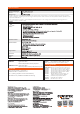
Opt.01
DA4 Interface (including cable, GTL-214)
Note : Optional DA4 interface must be installed in factory.
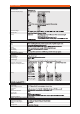
OPTION
OPTION ACCESSORIES
Test Fixture (including GTL-210 x 2, GTL-213 x 1)
Test Fixture (including GTL-210 x 2, GTL-213 x 1)
Test Lead, Banana to Bare-wire, Approx. 1000mm
Test Lead, Banana to Banana, Approx. 1000mm
Test Lead, O-Type to Bare-wire, Approx. 1000mm
Test Lead, O-Type to Banana, Approx. 1000mm
DA4 Cable, Approx. 1000mm
RS-232C cable, 9-pin Female to 9-pin, null
modem for computer, Approx. 2000mm
USB Cable, A-B type, Approx. 1200mm
GPIB Cable, Approx. 2000mm
Rack Mount Kit, 19” 2U size
GPM-001
GPM-001(EU)
GTL-209
GTL-210
GTL-212
GTL-213
GTL-214
GTL-232
GTL-246
GTL-248
GRA-422
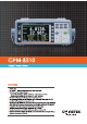
Digital Power Meter
with RS-232C/USB device & host/LAN/GPIB
Digital Power Meter
with RS-232C/USB device & host/LAN/GPIB and opt. DA4
GPM-8310
GPM-8310 with DA4
ORDERING INFORMATION
Safety Instruction Sheet x 1, Power cord x 1
Test lead GTL-209 x 1, Test lead GTL-212 x 1
CD x 1 (including complete user manual and USB driver)
DA4 cable GTL-214 (available for GPM-8310 with DA4 only)
ACCESSORIES
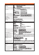
GENERAL
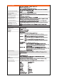
* Q (VAR), S (VA), λ (PF) and Φ (DEG) are originated from the measured values including voltage, current and active power which go through computation
process. In respect to distorted signal input, accordingly, the value acquired from other instruments, which employ different methods, may differ from that
acquired from GPM-8310 unit.
* “Zero” will be shown for S or Q and “--“ will be displayed for λ and Φ when either current or voltage is less than 0.5% of the rated range (less than or
equivalent to 1% when crest factor is set 6).
DIGITAL IO SIGNAL (OPTIONS)
Note
Item
I/O Control Output Signal
I/O Level
I/O Sink Current
Specification Condition
Operation Condition
Storage Condition
Power Source
Dimensions
Weight
SPECIFICATIONS