Programmable AC/DC Power Source ASR-2000 Series USER MANUAL ISO-9001 CERTIFIED MANUFACTURER
This manual contains proprietary information, which is protected by copyright. All rights are reserved. No part of this manual may be photocopied, reproduced or translated to another language without prior written consent of Good Will company. The information in this manual was correct at the time of printing. However, Good Will continues to improve products and reserves the rights to change specification, equipment, and maintenance procedures at any time without notice. Good Will Instrument Co., Ltd. No.
Table of Contents Table of Contents SAFETY INSTRUCTIONS .................................................. 5 GETTING STARTED .......................................................... 9 ASR-2000 Series Overview ................... 10 Appearance .......................................... 15 Theory of Operation ............................. 24 OPERATION .................................................................. 32 Set Up .................................................. 34 Menu Tree ................
ASR-2000 Series User Manual Simulate Mode ................................... 145 COMMUNICATION INTERFACE .................................... 159 Interface Configuration ...................... 160 FAQ .............................................................................. 180 APPENDIX .................................................................... 181 Firmware Update ............................... 181 Factory Default Settings ..................... 183 Error Messages & Messages ..............
SAFETY INSTRUCTIONS SAFETY INSTRUCTIONS This chapter contains important safety instructions that you must follow during operation and storage. Read the following before any operation to ensure your safety and to keep the instrument in the best possible condition. Safety Symbols These safety symbols may appear in this manual or on the instrument. WARNING Warning: Identifies conditions or practices that could result in injury or loss of life.
ASR-2000 Series User Manual Do not dispose electronic equipment as unsorted municipal waste. Please use a separate collection facility or contact the supplier from which this instrument was purchased. Safety Guidelines General Guideline CAUTION Do not place any heavy object on the ASR-2000. Avoid severe impact or rough handling that leads to damaging the ASR-2000. Do not discharge static electricity to the ASR2000. Use only mating connectors, not bare wires, for the terminals.
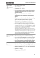
SAFETY INSTRUCTIONS Power Supply WARNING AC Input voltage range: 100 ~ 240 Vac Frequency: 47 ~ 63 Hz To avoid electrical shock connect the protective grounding conductor of the AC power cord to an earth ground. The power switch that is included in the instrument is not considered a disconnecting device. The power cord set is used as the disconnecting device and shall remain readily operable. Do not position the equipment so that it is difficult to operate the disconnecting device.
ASR-2000 Series User Manual (Pollution Degree) EN 61010-1:2010 specifies the pollution degrees and their requirements as follows. The ASR-2000 falls under degree 2. Pollution refers to “addition of foreign matter, solid, liquid, or gaseous (ionized gases), that may produce a reduction of dielectric strength or surface resistivity”. Pollution degree 1: No pollution or only dry, non-conductive pollution occurs. The pollution has no influence.
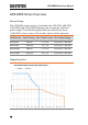
GETTING STARTED GETTING STARTED This chapter describes the ASR-2000 power supply in a nutshell, including its main features and front / rear panel introduction. ASR-2000 ASR-2000R ASR-2000 Series Overview ...................................... 10 Series lineup ...................................................................................... 10 Operating Area ................................................................................. 10 Main Features ............................................
ASR-2000 Series User Manual ASR-2000 Series Overview Series lineup The ASR-2000 series consists of 4 models, the ASR-2050, ASR-2100, ASR-2050R and ASR-2100R, differing only in capacity and front panel output. Note that throughout the user manual, the term “ASR-2000” refers to any of the models, unless stated otherwise. Model Name Power Rating Max. Output Current Max. Output Voltage ASR-2050 500 VA 5 / 2.5 A 350 Vrms / 500 Vdc ASR-2100 1000 VA 10 / 5 A 350 Vrms / 500 Vdc ASR-2050R 500 VA 5 / 2.
GETTING STARTED 11
ASR-2000 Series User Manual Main Features Performance 12 Maximum AC output voltage is 350 Vrms Maximum DC output voltage is 500 Vdc Maximum output frequency is 999.9 Hz in AC mode Supported AC+DC waveform application DC full capacity output ability Output voltage total harmonic distortion is less than 0.
GETTING STARTED Features Interface Include sine, square, triangle, arbitrary and DC output waveforms Variable voltage, frequency and current limiter Harmonic voltage and current analysis ability Excellent and feature-rich measurement capacity Sequence and simulate function External input amplification AC line synchronized output Preset memory function USB memory support Remote sense OCP, OPP and OTP protection function Built-in LAN, USB host and USB device in
ASR-2000 Series User Manual Factory Installed Options Optional Accessories Download 14 GTL-123 Test leads: 1x red, 1x black GTL-246 USB CABLE (USB 2.0 Type A- Type B Cable, Approx. 1.
GETTING STARTED Appearance Front Panel K 3 7 8 9 A 4 5 I F G M 1 6 L 2 B C J H D Item Index Description 1 Power switch button 2 USB interface connector (A Type) 3 LCD screen 4 Display mode select key 5 Function keys (blue zone) 6 Lock/Unlock button 7 V/V-Limit button 8 F/F-Limit button 9 Irms/IPK-Limit button A Range key/Output mode key E 15
ASR-2000 Series User Manual B Menu key/On phase key C Shift key D Test key/Output waveform key E Enter key F Preset key/Local mode key G Cancel key/ALM CLR key H Output key I Scroll wheel J Arrow keys K Air inlet L Hardcopy key M Output socket (ASR-2100/2050 only) 16
GETTING STARTED Item Description Power Switch Turn on the mains power USB A Port The USB port is used for data transfers and upgrading software. Also, it is available for screenshot hardcopy in association with the Hardcopy key.
ASR-2000 Series User Manual V V-Limit Used for setting the output voltage + F F-Limit Used for setting the output frequency (DC mode N/A) + Irms IPK-Limit + + 18 Selects between the AC+DC-INT, AC-INT, DC-INT, AC+DC-EXT, AC-EXT, AC+DCADD, AC-ADD, AC+DC-Sync and AC-Sync modes Enters the Main menu or goes back to one of the display modes.
GETTING STARTED Enter Key Confirms selections and settings Preset Key Puts the instrument into Preset mode Local Mode + Cancel Key ALM CLR Switches operation back to local mode from remote mode Used to cancel function setting menus or dialogs. + Clears alarms Hardcopy Key Used to take a screenshot by simply one press on the key. Make sure an USB flash disk in well inserted before the action. Output Key Turns the output on or off.
ASR-2000 Series User Manual Rear Panel 8 7 9 5 3 4 6 2 1 Item Index Description 1 Line input 2 Output terminal 3 Remote sensing input terminal 4 Exhaust fan 5 External I/O connector 6 External signal input/ External synchronized signal input 7 USB interface connector (B Type) 8 Ethernet (LAN) connector 9 Optional 1 interfaces (RS232C & GPIB connectors) 20
GETTING STARTED Item Description Line Input AC inlet Output Terminal Output voltage terminal (M3 screw type, 10 ~ 18 AWG) Remote Sensing Input Terminal Compensation of load wire voltage drop. Only +S and –S are available for compensation. N.C. terminals are N/A. Refer to page 98 for details. Exhaust Fan The exhaust fan is used to expel the heat from the unit. Please ensure there is at least 20 cm distance between any object and the fan.
ASR-2000 Series User Manual USB USB port for controlling the ASR-2000 remotely Ethernet Port The Ethernet port is used for remote control RS232C Connector The optional RS232C connector for controlling the ASR-2000 remotely (Factory Installed Optional 1) GPIB Connector The optional GPIB connector for controlling the ASR-2000 remotely (Factory Installed Optional 1) 22
GETTING STARTED Status Bar Icons Status bar / Status bar Indicates if the output is ON or OFF. Indicates the output power as a percentage of full scale. Indicates if the output range is 100V, 200V or AUTO. Indicates if the output waveform is Sine, Square, Triangle or ARB 1 - 16. The alarm icon will appear on the status bar when one of the protection functions is tripped. Indicates the shift key is pressed which enables shortcut operations with each key. Indicates that the ASR-2000 is under remote mode.
ASR-2000 Series User Manual Theory of Operation The theory of operation chapter describes the basic principles of operation, protection modes and important considerations that must be taken into account before use. Description of ASR-2000 System System block are composed of the parts described below. Input EMI Filter and PFC Circuit Auxiliary Power Isolation DC to DC Converter Output Power Stage (inverter) A two stage π filter and a passive PFC circuit that convert AC power to DC power.
GETTING STARTED Glossary Rate Output Maximum Power Capacity The maximum value of the output power capacity will be provided consecutively when the following situations exist: Output voltage is 100 to 175 V within the 100 V range. Output voltage is 200 to 350 V within the 200 V range. Output frequency is 40 to 999.9 Hz in AC mode. Output frequency is 1 to 999.9 Hz in AC+DC mode. Output voltage is 100 to 250 V within the 100 V range in DC mode.
ASR-2000 Series User Manual Equation: Maximum Peak Current (AC-INT mode only) The maximum value of the output current (peak value) will be provided consecutively to a capacitor input-type rectifying load when the following situations exist: Output voltage is 100 to 175 V within the 100 V range. Output voltage is 200 to 350 V within the 200 V range. Output frequency is 40 to 999.9 Hz in AC mode, and 1 to 999.9 Hz in AC+DC mode.
GETTING STARTED Crest Factor (CF) The crest factor stands for a ratio of the rms value correlated to the peak value (crest value) of the waveform. Equation: Note The crest factor is 1.41 of sine wave. Inrush Current Capacity It indicates the current, which is able to be supplied to a load, exceeds the rating for a short period and the duration. Output Power Ratio It indicates the output power of a percentage where the rated maximum output power is 100%.
ASR-2000 Series User Manual Abnormal Internal Control V-Limit F-Limit OCP OTP This alarm is activated and output will be disabled immediately when internal control abnormality is detected. Beware that all operations will be disabled except for the power shutdown operation if an error occurs. Voltage limit protection prevents a high voltage from damaging the DUT. This alarm can be set by the user. Frequency limit protection prevents a high frequency from damaging the DUT.
GETTING STARTED Considerations The following situations should be taken into consideration when using the power supply. Inrush Current Capacitive Load When the power supply switch is first turned on, an inrush current is generated. Ensure there is enough power available for the power supply when first turned on, especially if a number of units are turned on at the same time. When the power supply connects to a capacitive load, e.g.
ASR-2000 Series User Manual Inductive Load When the power supply connects to an inductive load, e.g., inductor, which generates a back EMF (Electromotive Force) when output current is accidentally turned off, a backflow diode is necessary for absorbing the back EMF, which may cause irreversible damage to the power supply. Refer to the following figure where a backflow diode connects with the inductive load in parallel to effectively absorb the possible back EMF.
GETTING STARTED Grounding The output terminals of the ASR-2000 series are isolated with respect to the protective grounding terminal. The insulation capacity of the load, the load cables and other connected devices must be taken into consideration when connected to the protective ground or when floating.
ASR-2000 Series User Manual OPERATION Set Up .................................................................... 34 Power Up ........................................................................................... 34 How to Use the Instrument ........................................................... 35 Output Terminals ............................................................................. 38 Installing GET-003/GET-004 Box Series (ASR-2000R only) 41 Using the Rack Mount Kit ....................
OPERATION Remote Sense ...................................................................... 98 Preset Settings................................................................................. 100 Save Preset Settings to Local Memory .......................... 100 Load Preset Settings to Local Memory ......................... 101 Manage Preset Settings ....................................................
ASR-2000 Series User Manual Set Up Power Up Steps 1. Connect the power cord to the rear panel socket. 2. Press the POWER key. The splash screen will appear momentarily before the continuous mode screen appears with the settings loaded. CAUTION The power supply takes around 15 seconds to fully turn on and shutdown. Do not turn the power on and off quickly.
OPERATION How to Use the Instrument Background The ASR-2000 AC power supplies generally use the scroll wheel, Arrow keys and Enter keys to edit numerical values or to select menu options. Menu navigation is performed using the menu keys and function keys on the front panel. The following section will explain some of these concepts in detail. Selecting Menu Items 1. Turn the scroll wheel to select parameters in menus and lists. The selected parameter will be highlighted in orange.
ASR-2000 Series User Manual Using the Arrow Keys and Scroll Wheel to Edit Parameter Values Use the Arrow keys to select a digit power and then use the scroll wheel to edit the value by that power. 1. Use the Arrow keys to move the cursor to the digit of the desired value. 2. Turn the scroll wheel to edit the value by the resolution of the selected digit. Cursor 3. Repeat the steps above for all the relevant digits. 4. Press the Enter key to confirm the edit.
OPERATION Using the Function Keys The function keys are quick settings keys, the function of which depends on the current menu or operation. 1. Press the Function key that corresponds to the setting directly to its left side. 2. The setting or parameter is immediately executed. Function keys Corresponding quick settings 3. Repeat the steps above for all the relevant digits.
ASR-2000 Series User Manual Output Terminals Background Supported Plugs The output terminals can be output from either the front panel or from the rear panel. The outputs are limited to 5 A / 2.5 A (ASR-2050), 10 A / 5 A (ASR-2100). Multi-region terminal socket Supported standards IEC, North America, Japan. EURO CEE type universal plug WARNING Dangerous voltages. Ensure that the power to the instrument is disabled before handling the power supply output terminals.
OPERATION WARNING Except for the AC-INT, AC-EXT and AC-Sync modes, the terminal outputs DC voltage as well. 3. Turn the power on. The AC power supply is now ready to power the DUT. The rear panel output is used to supply higher power DUTs. 1. Disconnect the unit from the mains power socket and turn the power switch off. 2. Remove the protective lid from the output terminals by loosening the screw. 3. Connect the output AC power wires to the AC output terminals.
ASR-2000 Series User Manual 4. Cover the protective lid onto the output terminals as the figure below shown. 5. Fasten the screw of protective lid with the unit. 6. Turn the power on. The AC power supply is now ready to power the DUT. Note WARNING 40 Grounded Neutral Output: ASR-2000 allows for a grounded return on the neutral output. It is suit for the medical industry that required between ground with neutral is 0 V essentially.
OPERATION Installing GET-003/GET-004 Box Series (ASR-2000R only) Background Optional Modules There are optional box series which are applicable to the ASR-2050R and ASR-2100R for additional power output socket in the front panel. GET-003 Universal Socket GET-004 European Socket WARNING Installation Dangerous voltages. Ensure that the power to the instrument is disabled before handling the GET003/004 installation. Failing to do so may lead to electric shock. 1.
ASR-2000 Series User Manual 3. Align the 2 hooks of GET-003/004 with the 2 rectangular grooves on the flank of ASR-2000R unit and slide GET-003/004 horizontally. 4. Gently slide the GET-003/004 into place until click to have it level with ASR-2000R evenly. 5. Fasten the 2 screws in the rear side of GET-003/004 with bare hands easily.
OPERATION 6. Connect the output AC power wires from the GET-003/004 to the AC output terminals. Red Line (L) Black Neutral (N) Green GND ( ) 7. Cover the protective lid back to the output terminals followed by fastening the screw of protective lid with the unit. 8. GET-003/GET-004 is well assembled with the ASR-2000R unit.
ASR-2000 Series User Manual Using the Rack Mount Kit Background The ASR-2000 and ASR-2000R have the following optional Rack Mount kits, respectively. Unit Model ASR-2000 ASR-2000R ASR-2000 ASR-2000R Rack Mount kit part number GRA-439-E GRA-439-J The GRA-439-E is designed to fit into an EIA rack of 3U-height, while the GRA-439-J is designed to fit into a JIS rack of 3U-height. Please see your distributor for further rack mount details.
OPERATION GRA-439-J Series GRA-439-J Rack Mount Diagram (ASR-2000) GRA-439-J Rack Mount Diagram (ASR-2000R) GRA-439-J Rack Mount Diagram (Dual ASR-2000Rs) CAUTION Ensure adequate ventilation is provided when using the rack mount. Ensure that a gap is given for air intakes. Failure to do so may cause the instrument to overheat.
ASR-2000 Series User Manual Reset to Factory Default Settings Background Steps The default settings can be restored from the Menu key settings. See page 183 for the default factory settings. 1. Press the Menu key. The Menu settings will appear on the display. 2. Use the scroll wheel to go to item 8, Default Setting. 3. Press Enter for 2 times to restore the unit back to the default settings.
OPERATION View Firmware Version and Serial Number Background Steps The Menu>System Information setting displays the serial number and firmware version. 1. Press the Menu key. The Menu setting will appear on the display. 2. The system information should now be listed in the item 1, System Information, on the display Exit 3. Press Exit[F4] to exit from the Menu settings.
ASR-2000 Series User Manual LCD Configuration Background Steps The LCD Configuration setting sets the brightness, contrast and saturation level of the LCD display. 1. Press the Menu key. The Menu settings will appear on the display. 2. Use the scroll wheel to go to item 7, LCD Configuration and press Enter. 3. Set the brightness, contrast and saturation. Contrast(%) 1 ~ 100% (Default=50%) Brightness(%) 1 ~ 100% (Default=50%) Saturation(%) 1 ~ 100% (Default=50%) Exit 4.
OPERATION USB Driver Installation Background Note If the USB Type B interface is to be used for remote control, the USB driver needs to be installed. The USB driver, gw_asr.inf, can be downloaded from the GW Instek website. For information on the USB interface, see page 161. Steps 1. Connect the rear panel USB -B port on the ASR-2000 to the PC using a USB Type A to B cable. 2. Go the Windows Device Manager.
ASR-2000 Series User Manual 4. From the hardware wizard choose Browse my computer driver software. 5. Set the file path to the location of the USB driver, click Next and finish the driver installation. 6. ASR-2000 will now be located in the Ports node of the hardware tree in the Windows Device Manager if the driver installation was successful.
OPERATION Filter Installation Background Steps The ASR-2000 has a filter (GW Instek part number, ASR-001) that must first be inserted under the control panel before operation. 1. Loose the screw embedded beneath the air inlet as indicated within the figure below. 2. Pull the frame of air inlet outward from the bottom side to detach it from unit.
ASR-2000 Series User Manual 3. Remove the frame of air inlet followed by gently putting it aside. 4. The air filter is positioned in the rear side of frame of air inlet. Simply rinse it or replace the filter with a new one based on the actual status. 5. Repeat the previous steps conversely to reinstall the air inlet with new filter back to unit. 6. The unit is now ready to power up. Note Please clean regularly to avoid damaging the internal components of the machine.
OPERATION Wire Gauge Considerations Background Before connecting the output terminals to a load, the wire gauge of the cables should be considered. It is essential that the current capacity of the load cables is adequate. The rating of the cables must equal or exceed the maximum current rated output of the instrument. Recommended Wire Gauge Wire Gauge Nominal Cross Maximum Current Section 20 0.5 9 18 0.75 11 18 1 13 16 1.5 18 14 2.
ASR-2000 Series User Manual To minimize noise pickup or radiation, the load wires and remote sense wires should be twistedpairs of the shortest possible length. Shielding of the sense leads may be necessary in high noise environments. Where shielding is used, connect the shield to the chassis via the rear panel ground screw. Even if noise is not a concern, the load and remote sense wires should be twistedpairs to reduce coupling, which might impact the stability of the power supply.
OPERATION Menu Tree Convention Use the menu trees as a handy reference for the power supply functions and properties. The ASR-2050 / ASR2050R / ASR-2100 / ASR-2100R menu system is arranged in a hierarchical tree. Each hierarchical level, which is coated in varied colors, can be navigated through the orders within the diagrams below. For example: To set the interface to Buzzer OFF; 1 Press the Menu key. ○ 2 Navigate to the MISC Configuration option. ○ 3 Enter the Buzzer option. ○ 4 Select OFF.
ASR-2000 Series User Manual Main Page Main Page MODE AC+DC-INT ACV DCV FREQ IRMS ON phs OFF phs WAVE FIXED FIXED SIN FREE FREE SQU Test SEQ TRI ARB 1~16 AC-INT ACV FREQ IRMS ON phs OFF phs WAVE Test FIXED FIXED SIN SEQ FREE FREE SQU SIM TRI ARB 1~16 DC-INT DCV I Test SEQ AC+DC-EXT GAIN IRMS AC-EXT GAIN IRMS AC+DC-ADD ACV DCV FREQ IRMS GAIN ON phs OFF phs WAVE FIXED FIXED SIN SQU FREE FREE TRI ARB 1~16 AC-ADD ACV FREQ IRMS GAIN ON phs OFF phs WAVE
OPERATION Function Keys AC+DC-INT, AC+DC-EXT, AC-EXT, AC+DC-ADD, AC-ADD Function Keys F1 V Vavg Vamx P S Q I Iavg Iamx IpkH PF CF P S Q PF CF Vmin F2 Imin F3 IpkH F4 RUN HOLD AC-INT Function Keys F1 V Vavg Vamx Vmin P S Q THDv I Iavg Iamx Imin IpkH PF CF THDi P S Q IpkH PF CF F2 F3 F4 RUN HOLD 57
ASR-2000 Series User Manual DC-INT Function Keys F1 V Vavg Vamx Vmin Iavg Iamx Imin Vmin P F2 I IpkH F3 P IpkH F4 RUN HOLD AC+DC-Sync, AC-Sync Function Keys F1 V Vavg Vamx P S Q I Iavg Iamx IpkH PF CF P S Q PF CF Freq F2 Imin F3 F4 RUN HOLD 58 IpkH
OPERATION Menu Menu System Information MISC Configuration T Ipeak, hold Ipkh CLR EXEC Output Relay THD Format Power ON Buzzer Remote Sense Slew Rate Mode ON ON ON Time OFF OFF OFF Slope Enable IEC SEQ Disable CSA SIM LAN DHCP IP Address Subnet Mask Gateway Databits Parity Stopbits DNS Socket Port ON OFF USB Device Speed Full Auto RS232C*1 Baudrate 9600 (default) 8bits (default) None (default) 1bits (default) GPIB*1 Address 10 (default) LCD Configuration Contrast(%) Brig
ASR-2000 Series User Manual Basic Operation This section describes the basic operations required to operate the power supply.
OPERATION Select the Output Mode Background Steps The ASR-2000 has up to 9 modes to output, which empower user to have multiple applications for different scenarios. 1. Press Shift + Range to access the MODE selection menu. + Alternatively, it is available to use scroll wheel followed by the Enter key to enter the MODE menu. 2. Choose an output mode with scroll wheel.
ASR-2000 Series User Manual Select the Voltage Range Background Steps The Range setting determines the general outlet voltage range. The ranges available correspond to common mains output voltage standards. 1. Press Range to access the Range menu. 2. Set the voltage range with the F1 ~ F4 softkeys. F1: AUTO Soft-keys F3: 200V F4: 100V 3. Press Enter to confirm the Range setting.
OPERATION Select the Output Waveform Background Steps The ASR-2000 is capable of outputting sine, square, triangle and ARB wave shapes while connecting with external signals. 1. Press Shift + Test to access the Wave menu. + Alternatively, it is available to use scroll wheel followed by the Enter key to enter the Wave menu. 2. Choose a waveform with scroll wheel. Mode Description SIN Sine wave SQU Square wave TRI Triangle wave ARB 1 ~ 16 Arbitrary wave 1 ~ 16 3.
ASR-2000 Series User Manual Wave setting Note 64 Waveform selection is Not available under DCINT, AC+DC-EXT and AC-EXT output modes. For more details about Arbitrary waveforms, refer to the page 110. When changing to a waveform with setting higher than the upper limit of other waveform, the setting of other waveform will be adjusted to zero forcibly. For instance, when it is originally SIN output with ACV in 150 Vrms (175 Vrms for V-Limit), the ACV will be changed to 0 Vrms (144.
OPERATION Setting the Output Voltage Limit Background Steps Setting the voltage limit allows the output voltage to be set to any level within the voltage limit range. 1. Press Shift + V to access the Volt Limit menu. + 2. When it is under AC+DC-INT, DC-INT, AC+DC-ADD or AC+DC-Sync mode. Use the scroll wheel to toggle between VPK+ (upper) and VPK- (lower) settings followed by pressing Enter to get into the parameter. Proceed to the step 3 for setup.
ASR-2000 Series User Manual When it is under AC-INT, AC-ADD or ACSync mode. Use the scroll wheel to set value of Vrms limit directly or use the F3 (MAX) and F4 (MIN) softkeys to set the limit to the maximum or minimum value.
OPERATION Soft-keys MAX, MIN VPK+ Setting VPKSetting Both the VPK+ and VPK- Limit values defined by user will be generally applied to AC+DC-INT, DCINT, AC+DC-ADD and AC+DC-Sync modes under the same voltage range, which divides into 2 levels, high range including AUTO and 200V and low range covering 100V. Note 4. Press Enter to confirm the voltage limit setting. Note Voltage limit setting is Not available for both AC+DC-EXT and AC-EXT output modes. There 4 sets of voltage limits in total.
ASR-2000 Series User Manual Setting the Output AC/DC Voltage & Gain Background Steps The ACV, DCV and Gain settings set the output voltage level. Before setting the power supply voltage level, set the voltage range and voltage limit beforehand. 1. Press the V key. The ACV parameter will be selectable. Also, it is available to use the scroll wheel followed by the Enter key to make the ACV parameter selectable as well. When it is under AC+DC-INT, AC+DC-ADD or AC+DC-Sync mode.
OPERATION 2. Set ACV/DCV/GAIN value with the scroll wheel or with the F1 ~ F4 soft-keys.
ASR-2000 Series User Manual 5. Press and hold either the DEF1 or DEF2 softkey until “Saved to DEF1/2” is displayed, which indicates the voltage and gain settings are saved to the DEF1 or DEF2 soft-key individually. Note Trying to set the voltage outside of the voltage limit/range will result in a voltage setting error being displayed on the screen. ACV, DCV and GAIN settings under each output mode and range have their own DEF1 and DEF2 saved values, respectively.
OPERATION Setting the Frequency Limit Background Steps Setting the frequency limit allows the frequency output to be set to any level within the limit range. 1. Press Shift + F to access the Freq Limit menu. + 2. Use the scroll wheel to toggle between Freq Hi (upper) and Freq Lo (lower) settings followed by pressing Enter to get into the parameter. Freq Hi Setting Freq Lo Setting 3. Set the frequency limit with the scroll wheel or with the F3 ~ F4 soft-keys.
ASR-2000 Series User Manual AC+DC-INT, AC+DC-ADD Freq Range Hi Soft-keys Limit 1.00 ~ 999.9 Hz Freq Range Lo Soft-keys Limit 1.00 ~ 999.9 Hz MAX, MIN MAX, MIN Freq Hi Setting Freq Lo Setting AC-INT, AC-ADD Freq Range Hi Soft-keys Limit 40.00 ~ 999.9 Hz Freq Range Lo Soft-keys Limit 40.00 ~ 999.
OPERATION Freq Lo Setting 4. Press Enter to confirm the limit setting. Freq Limit setting Min/Max settings Example of Freq Hi Limit Setting in AC+DC-INT F3 F4 Note Frequency limit setting is Not available under DC-INT, AC+DC-EXT, AC-EXT, AC+DC-Sync and AC-Sync output modes. Before change freq limit setting, if FREQ setting value is bigger than desire freq limit value, the freq limit value cannot be change accordingly.
ASR-2000 Series User Manual Setting the Output Frequency & Signal Background Steps The FREQ and SIN settings set the frequency of the output. Before setting the frequency, set the frequency limit. 1. Press the F key to access the FREQ or SIG parameter depending on varied modes. Also, it is available to use the scroll wheel followed by the Enter key to make the FREQ or SIG parameter selectable as well. 2. Set the frequency or signal with the scroll wheel or with the F1 ~ F4 soft-keys.
OPERATION 4. Repeat the previous steps 1 ~ 2 to set frequency with the scroll wheel. 5. Press and hold the DEF1 or DEF2 soft-key until “Saved to DEF1/2” is displayed. This will save the frequency setting to the DEF1 or DEF2 soft-key individually.
ASR-2000 Series User Manual Setting the Peak Current Limit Background Note Steps Setting the peak current limit sets a limit on the current that can be sourced by the power supply. Once the output current over the setting, the output will set to off. When the peak current limit is tripped, an alarm will sound. Press Shift + Cancel to clear the Ipk alarm. 1. Press Shift + Irms to access the IPK Limit menu. + 2.
OPERATION 3. Set the peak current (IPK+ & IPK-) with the scroll wheel or with the F3 (MAX) and F4 (MIN) soft-keys to set the current limit to the maximum and minimum values, respectively. AC+DC-INT, AC–INT, DC-INT, AC+DC-EXT, AC–EXT, AC+DC-ADD, AC–ADD, AC+DCSync, AC-Sync IPK+ IPK- Range 10.5 ~ 105% of rate peak current Soft-keys IPK Limit On/Off, MAX, MIN Range -105 ~ -10.
ASR-2000 Series User Manual IPK Limit On/Off IPK Limit On In theory, It is the function which keeps the IPK limits (+ & -) within the certain range when the predefined values are reached. If, however, this function is turned off, the output will be disabled instantly when either IPK+ or IPK- limit is reached. 4. After entering the either IPK+ Limit or IPK- Limit setting, press F1 soft key to turn IPK Limit function On. Load On Kept within IPK Limit On Level IPK Limit ON: T I IPK Limit Off 5.
OPERATION Setting the Output Current Level Background Steps The IRMS and I settings set the current of the output. Setting the RMS or AVG current sets a limit on the current that can be sourced by the power supply. Once the output current is over the setting, the output will set to off. 1. Press Irms to access the IRMS or I menu depending on varied modes. Also, it is available to use the scroll wheel followed by the Enter key to make the IRMS or I parameter selectable as well. 2.
ASR-2000 Series User Manual I setting Soft-keys setting F1 Example of I Setting in the DC-INT F3 F4 IRMS & I Limit On/Off IRMS & I Limit On Almost identical with the concept of previous IPK Limit function, the IRMS/I Limit function keeps the IRMS/I value within the certain limit when the predefined value is reached. However, due to RMS calculation, the unit requires approximate 200ms of detect time before starting the adjustment process so that the IRMS/I limit can be well maintained.
OPERATION IRMS & I Limit Off 4. After entering the either IRMS or I setting, press F1 soft key to turn IRMS Limit function Off. Load On IRMS & I Limit OFF: I IRMS or I Limit Off Level is reached. Turn the Output Off Immediately. T 5. Press Enter to confirm the IRMS/I setting.
ASR-2000 Series User Manual Setting the Output On Phase Background Steps The on phase setting sets the starting phase of the voltage output. 1. Press Shift + Menu to make the ON Phs parameter selectable. + Also, it is available to use the scroll wheel followed by the Enter key to make the ON Phs parameter selectable as well. 2. Set the ON Phs setting with the scroll wheel or with the F3 (MAX) and F4 (MIN) soft-keys to set the On Phase to the maximum and minimum values, respectively.
OPERATION On Phase setting Soft-keys setting F1 Example of On Phase Setting F3 F4 FIXED & FREE Modes Pressing the F1 key to toggle between modes of FIXED, which indicates the user-defined on-phase degree, or FREE, which represents the degree of onphase is freely determined by the unit itself. When FREE is selected, the both F3-MAX and F4-MIN keys are grayed out, signaling the unavailability by user.
ASR-2000 Series User Manual Setting the Output Off Phase Background Steps The off phase setting sets the ending phase of the voltage output. 1. Use the scroll wheel followed by the Enter key to make the OFF Phs parameter selectable. 2. Set the OFF Phs setting with the scroll wheel or with the F3 (MAX) and F4 (MIN) soft-keys to set the Off Phase to the maximum and minimum values, respectively. AC+DC-INT, AC-INT, AC+DC-ADD, AC-ADD, AC+DC-Sync, AC-Sync OFF Phs Range 0.0° ~ 359.
OPERATION OFF Phase setting Soft-keys setting F1 Example of OFF Phase Setting F3 F4 FIXED & FREE Modes Pressing the F1 key to toggle between modes of FIXED, which indicates the user-defined off-phase degree, or FREE, which represents the degree of offphase is freely determined by the unit itself. When FREE is selected, the both F3-MAX and F4-MIN keys are grayed out, signaling the unavailability by user.
ASR-2000 Series User Manual Switch the Display Modes The ASR-2000 power supply has three display modes. The standard display mode shows the power supply setup in the middle and the 3 configurable measurements on the right that correspond to the far-left live-time measurements section. The simple display mode shows all measurement items available on the ASR-2000 with 3 measurement formats switchable at any time.
OPERATION Simple Mode Measurement Items Simple/Harm Measuremt formts Hold measurement Configuring the Simple Mode Measurements 1. Press the F2 (RMS/AVG/PEAK) soft-key to toggle among each mode of format. 2. The display will show parameters of measurement for each format. Refer to the page 92 for details. Harmonic Mode Measurement Items Simple/Harm THDv/THDi Page Up Page Down Configuring the Harmonic Mode Measurements 1.
ASR-2000 Series User Manual 3. When the measurements are beyond one page, which consists of up to 10 items, press the F3 (Page Up) and F4 (Page Down) soft-keys to flip through pages. Hold Measurement Note 88 Press the soft-key F4 to toggle hold on or off. This function will “hold” the current measurements on the display, which means the measurements won’t be updated until the function is released. Hold measurement is available for the Standard and Simple display modes only.
OPERATION Using the Measurement Function The 3 configurable measurements, which indicate the live-time measurement in varied units, on the far-right side within the standard display mode can be switched by user anytime in the process of power output, thus providing an instantaneous analysis. Steps 1. Press the Display key to switch to the Standard display mode. 2. Press the F1(ITEM1), F2(ITEM2) or F3(ITEM3) soft-key to enter each menu. 3.
ASR-2000 Series User Manual Example of ITEM1 in AC+DCSync ITEM1 options ITEM 2 I Root Mean Square Current Iavg Average Current Imax Positive Peak Current Imin Negative Peak Current IpkH Peak Current Hold PF Power Factor (n/a in DC-INT mode) Crest Factor (n/a in DC-INT mode) CF THDi Total Harmonic Distortion Current (available in AC-INT mode only) Example of ITEM2 in AC+DCSync ITEM2 options ITEM 3 90 P Real Power S Apparent Power (n/a in DC-INT mode) Q Reactive Power (n/a in DC-INT m
OPERATION PF CF Freq Example of ITEM3 in AC+DCSync Note Power Factor (n/a in DC-INT mode) Crest Factor (n/a in DC-INT mode) Frequency (available in AC+DC-Sync and ACSync modes only) ITEM3 options Each output mode has varied measurement functions display. Refer to the above tables for detailed options.
ASR-2000 Series User Manual Switch the Measurement Format The 3 measuring formats, RMS, AVG as well as PEAK, on the farright side within the simple display mode can be switched by user anytime in the process of power output, thus offering an instant readout of diversified calculations. Steps 1. Press the Display key to switch to the Simple display mode. 2. Press the F2 (RMS/AVG/PEAK) soft-key to toggle among each mode of format.
OPERATION Vmax/ Vmin & Imax/ Imin Values PEAK Display All output modes except DC-INT V&I RMS Values Vavg & Iavg Values Vmax/ Vmin & Imax/ Imin Values Note RMS Display AVG Display PEAK Display The selected measurement format will be merely shown in the Simple display mode, for which refer to page 87 for further details.
ASR-2000 Series User Manual Panel Lock The panel lock feature prevents settings from being changed accidentally. When activated, all keys and knobs except the Lock/Unlock key and the Output key (if active) will be disabled. If the instrument is remotely controlled via the USB/LAN/RS232/GPIB interface, the panel lock is automatically enabled. See page 159 for remote control details. Activate the Panel Lock Press the Lock key to active the panel lock. “Keys locked” appears on the display.
OPERATION Alarm Clear Background Steps The ALM CLR (Alarm Clear) function will clear alarms like Over Current, Over Peak Current, Over Temperature, AC fail, Fan fail, Remote Sense Error, among others. Refer to page 187 for more details. 1. Press Shift + Cancel to clear any alarms.
ASR-2000 Series User Manual Turning the Output On/Off When the output is turned on, the DUT can be connected to either the rear panel output or the front panel output. WARNING Turn Output On Turn Output Off 96 Both of these outputs are electrically linked. Only one DUT should be connected to any one of the outputs at a time. Using both outputs at the same time is not supported. Using the front and rear outputs at the same time could cause dangerous operating conditions.
OPERATION Advanced Settings Using the Remote Sense Function → from page 97 Preset Settings → from page 100 Using the Remote Sense Function The ASR-2000 can be operated using local or remote voltage sense. By default, the power supply is configured for local sense. WARNING Ensure the output is off before handling the remote sense connectors. Use sense cables with a voltage rating exceeding the isolation voltage of the power supply. Never connect sensing cables when the output is on.
ASR-2000 Series User Manual Remote Sense Remote Sense Operation Remote sense is used to compensate for the voltage drop seen across load cables due to resistance inherent in the load cables. The remote sense function can compensate a maximum of 5% of the output voltage and all of output frequency. 1. Configure the remote sense setting to ON (page 121). 2. Connect the Neutral terminal of the remote sense terminal block to the Neutral terminal of the load. 3.
OPERATION Note Do Not connect any wires to the N.C terminals of the remote sense terminal block. 4. After well connecting, cover the protective lid onto the remote sensing input terminal block followed by fastening the screw as figure shown below. 5. The remote sense connection along with the protective lid is therefore well set up.
ASR-2000 Series User Manual Preset Settings Save Preset Settings to Local Memory Up to 10 preset settings can be saved to internal memory. Steps 1. Press Preset followed by clicking with holding on the F1 ~ F4 soft-keys individually to save the present settings to the corresponding memory number. Presets + (hold) M0 ~ M3 2. Press the Preset key again to exit from the preset mode. Example Note For example, pressing Preset & holding F1 will save the present settings to memory slot 0 (saved to M0).
OPERATION Load Preset Settings to Local Memory Any of the 10 preset settings can be recalled from internal memory. Steps 1. Press Preset followed by clicking on the F1 ~ F4 soft-keys individually to load the corresponding memory number. Presets + M0 ~ M3 2. Press the Preset key again to exit from the preset mode. Example Note For example, pressing Preset + F1 will recall the saved settings from memory slot 1 (recalled from M0).
ASR-2000 Series User Manual Manage Preset Settings Preset settings can be easily saved to or recalled from a USB flash drive using the Save/Recall Files utility in the Menu system. Settings can also be deleted from local memory using the utility. File Format When files are saved to USB they are saved in the following format: PresetX.Set, where X is the memory number M0 ~ M9. The files are saved to USB:/gw. When files are recalled from USB, files must be recalled from the same memory number.
OPERATION Save Saves the selected preset memory to local memory. Recall Recalls the selected preset memory from local memory. 5. Go to the Memory No. setting and select the preset memory number to perform the operation on. Press Enter to confirm. Memory No. 0 ~ 9 (M0 ~ M9) Execute File Operation 6. Press EXE[F1] to perform the selected file operation. Exit 7. Press EXIT[F4] to exit from the Save/Recall Files settings. Example Load file from USB to Local memory Memory No.
ASR-2000 Series User Manual Example MEMUSB Loads all the files including Preset, Sequence, Simulate and ARB from a USB flash drive to the local memory. Delete Deletes all the files including Preset, Sequence, Simulate and ARB from local memory.
EXTERNAL CONTROL EXTERNAL CONTROL The rear panel has 3 signal output connectors. These connectors are used for external control from the menu of this product by using the external signal that includes amplified external voltage, amplified external signal as well as synchronization frequency. Note that prior to operation, it is required to implement insulation process for external circuit.
ASR-2000 Series User Manual Using External Control I/O The External Control I/O is primarily used to control ASR-2000 externally by using the logic signal. More than that, it is able to monitor Sequence function status remotely with ease. Overview Specification Control input High level: +2.2 V or higher Low level: +1.0 V or lower Non-destructive maximum input: +7 V / -5 V Input Impedance: Pulled up to +5 V with 47 kΩ Status output Pin Assignment Pin No.
EXTERNAL CONTROL 18 19 20 21 22 23 24 25 GND Output Output Output Output Output Output Output Note +5 V Reserved Reserved Reserved Reserved Reserved Reserved 50 mA or less The limiter operation is recognized as On when the following conditions exist. Output peak current limiter (positive) is operated. Output peak current limiter (negative) is operated. Output average current limiter is operated. Output power limiter is operated.
ASR-2000 Series User Manual EXT GAIN - AC+DC-EXT and AC-EXT mode Overview External Input Gain Range Equation Select AC+DC-EXT or AC-EXT mode to use ASR-2000 as an amplifier specifically for signal input from the external signal input port on the rear panel. The impedance of input is 1MΩ, whilst the frequency range of input is from DC to 999.9 Hz. External Input Gain Setting 100V Range 200V Range Setting Range 0.0 to 250.0 0.0 to 500.0 Resolution 0.1 0.1 Initial Value 100.0 200.
EXTERNAL CONTROL EXT ADD - AC+DC-ADD and AC-ADD mode Overview & Concept Select AC+DC-ADD or AC-ADD mode to add the external signal source signal that includes magnification to the internal signal then power output on the rear panel. The impedance of input is 1MΩ, whilst the frequency range of input is from DC to 999.9 Hz.
ASR-2000 Series User Manual Compiling Arbitrary Waveform Input Background Note Memory In order to generate arbitrary waveforms, it is requested to use a specifically control software on external PC which transfers data, via USB interface, to the arbitrary waveform memory with ASR-2000. Arbitrary waveforms cannot be changed when output is on. To change arbitrary waveform, make sure the output is off beforehand. It is not allowed to compile the arbitrary waveform memory directly from ASR-2000.
EXTERNAL CONTROL 2. Choose one of the ARB waveforms (ARB 1 to ARB 16) with scroll wheel. Default Waveform Setting ARB 1 - 8 SIN waveform ARB 9 - 12 SQU waveform ARB 13 - 16 TRI waveform 3. Press Enter to confirm the waveform setting. Example ARB 16 selected Note When the input peak value of ARB waveform is not in the full scale 32768, the ratio of maximum value of voltage output by ARB waveform will decrease accordingly.
ASR-2000 Series User Manual Manage Arbitrary Waveform Settings Arbitrary waveform settings can be easily saved to or from a USB flash drive using the Save/Recall Files utility in the Menu system. Files can also be deleted from local memory using the utility. File Format When files are saved to USB they are saved in the following format: ARBX.ARB, where X is the memory number 1 ~ 16 (ARB0 ~ ARB16). The files are saved to USB:/gw.
EXTERNAL CONTROL Deletes the selected ARB memory from local memory. Delete 5. Go to the Memory No. setting and select the sequence memory number to perform the operation on. Press Enter to confirm. Memory No. 1 ~ 16 (ARB1 ~ ARB16) Execute File Operation 6. Press EXE[F1] key to perform the file operation. Exit 7. Press EXIT[F4] key to exit from the Save/Recall Files settings. Example Load file from USB to Local memory Memory No. 1 selected All Data Operation 8.
ASR-2000 Series User Manual Example MEMUSB Loads all the files including Preset, Sequence, Simulate and ARB from a USB flash drive to the local memory. Delete Deletes all the files including Preset, Sequence, Simulate and ARB from local memory. All Data option selected Save all data from Local memory to USB Single Arbitrary Wave Default From the previous step 4, execute the “Delete” action to restore the selected ARB memory back to the default setting.
MISCELLANEOUS MISCELLANEOUS The Miscellaneous menu contains miscellaneous parameter settings. T Ipeak, hold ......................................................... 116 Ipkh CLR ................................................................ 118 Power ON .............................................................. 119 Buzzer ................................................................... 120 Remote Sense ........................................................ 121 Slew Rate Mode ..................
ASR-2000 Series User Manual T Ipeak, hold The T Ipeak, hold function sets the hold time for the peak current measurement. After the output is turned on, the ASR-2000 will delay starting the peak current measurement by this hold time. Concept in diagram Output on Hold the peak current measurement value Ipeak Hold time I Note Steps T The hold peak current will be updated when new measurement is greater than the previous value.
MISCELLANEOUS Exit 4. Press Exit[F4] to exit from the MISC Configuration settings.
ASR-2000 Series User Manual Ipkh CLR The peak current measured during output process can be easily cleared out via this function. It is applicable for user to restart measuring the peak current value when necessity emerges. Steps 1. Press the Menu key. The Menu setting will appear on the display. 2. Use the scroll wheel to go to item 2, MISC Configuration and press Enter. 3. Go to the Ipkh CLR setting using the scroll wheel and press Enter on the EXEC button.
MISCELLANEOUS Power ON The Power ON setting allows you to have the power-on output or other operation functions on automatically after startup. The settings that are loaded are the last settings that were present in the standard mode before the unit was turned off last. Steps 1. Press the Menu key. The Menu setting will appear on the display. 2. Use the scroll wheel to go to item 2, MISC Configuration and press Enter. 3. Go to the Power ON setting using the scroll wheel and press Enter.
ASR-2000 Series User Manual Example Power ON setting Buzzer The Buzzer setting turns the buzzer sound on or off for key presses. Steps 1. Press the Menu key. The Menu setting will appear on the display. 2. Use the scroll wheel to go to item 2, MISC Configuration and press Enter. 3. Go to the Buzzer setting using the scroll wheel and press Enter. Turn the setting on or off and press Enter again to confirm. Buzzer ON, OFF 4. Press Exit[F4] to exit from the MISC Configuration settings.
MISCELLANEOUS Remote Sense The remote sense function detects the output voltage at the sensing input terminal. This function compensates for voltage drops across the load cables when the load is connected to the ASR-2000 over a long distance. Note Steps The remote sense function can compensate a maximum of 5% of the output voltage. The maximum output voltage when compensation is used is limited by the rated voltage. 1. Press the Menu key. The Menu setting will appear on the display. 2.
ASR-2000 Series User Manual Display When the remote sense function is on, the displayed voltage value is the voltage measured at the sense terminal and the symbol “SENS” is displayed on the status bar for standard and simple mode display. SENS displayed WARNING Before connecting the remote sense cables, turn off the output and peripherals. Please see page 97 for more information on the remote sense cabling instructions.
MISCELLANEOUS Slew Rate Mode The slew rate, which is described as the fluctuating change of voltage per unit of time, can be customized by user in the 2 modes containing Time and Slope elaborated below for ASR-2000 models. Steps 1. Press the Menu key. The Menu setting will appear on the display. 2. Use the scroll wheel to go to item 2, MISC Configuration and press Enter. 3. Go to the Slew Rate Mode setting using the scroll wheel and press Enter. Choose the slew rate mode and press Enter again to confirm.
ASR-2000 Series User Manual Voltage drop occurs in output voltage due to the set waveform or frequency under the Slope mode. It is suggested to adopt the Time mode when precise sine wave voltage output is required. Example Slew Rate setting Output Relay The internally built-in output relay function has close relation with the power output function by default.
MISCELLANEOUS Exit 4. Press Exit[F4] to exit from the MISC Configuration settings. Example Output Relay setting THD Format Choose one of the THD (Total Harmonic Distortion) equations. The equations of 2 varied modes (IEC by default) of Harmonic Format below are for, specifically, by the time the upper limit of measured harmonic order is 40. Steps 1. Press the Menu key. The Menu setting will appear on the display. 2. Use the scroll wheel to go to item 2, MISC Configuration and press Enter. 3.
ASR-2000 Series User Manual IEC & Equation The ratio of rms value of the second to the 40th harmonic component is computed to that of the fundamental. CSA & Equation The ratio of rms value of the second to the 40th harmonic component is computed to that of the rms value of the first to 40th component.
MISCELLANEOUS Example THD Format setting External Control I/O User can enable or disable the External Control I/O input. When External Control I/O input is set as disabled, the ASR-2000 series status will remain output. Steps 1. Press the Menu key. The Menu setting will appear on the display. 2. Use the scroll wheel to go to item 2, MISC Configuration and press Enter. 3. Go to the External Control setting using the scroll wheel and press Enter.
ASR-2000 Series User Manual TEST MODE FUNCTION There are two test modes, Sequence Mode and Simulate Mode respectively, available for user to execute. Refer to the following chapters for details in necessity. Sequence Mode ..................................................... 129 Sequence Mode Overview ............................................................ 129 Sequence Settings ........................................................................... 134 Save a Sequence to Local Memory ............
TEST MODE FUNCTION Sequence Mode Sequence Mode Overview Background The Sequence function works with DC-INT, ACINT and AC+DC-INT modes with full AC waveforms containing sine, square, triangle as well as arbitrary. The available parameters, which will be introduced in later sectors, vary depending on selected output modes. A Sequence function is comprised of up to the maximum 999 steps.
ASR-2000 Series User Manual Step Time ACV Assigns the step number. Sets the step duration time. This step time is exclusive of any transition time needed to match start phases and stop phase. See the diagram on page 133 for details. Sets the AC voltage level. There are 3 secondary voltage settings that determine how the voltage is output. CT: Sets the voltage level of the step immediately to ACV values. KP: Sets the voltage level to “keep” the voltage of the previous step.
TEST MODE FUNCTION AC/DC Voltage There are 2 voltage range settings: Range (ACV/DCV) HI 200V & LO 100V, which result in varied ranges of ACV and DCV values, respectively. Fset (Frequency) Sets the frequency of the step. There are 3 secondary frequency settings that determine how the frequency is output. CT: Sets the frequency level of the step immediately to Fset values. KP: Sets the frequency level to “keep” the frequency of the previous step.
ASR-2000 Series User Manual Branch1/ Branch2 The Branch settings allow you to make a selectable branch within the sequence when the sequence is running or on hold. The branch1 or branch2 actions are enabled by pressing the F1 or F2 function keys, or by using the :TRIG:SEQ:SEL:EXEC remote control command. After the branch step(s) have completed the unit will return back to the step from which the branch was executed and continue to run the step from where it left off.
TEST MODE FUNCTION Time of step Sequence Example Time of step Time of next step ON Phs OFF Phs ON Phs Step 1 Jump Cnt=0 Sequence Flow Example Step 1 Jump Cnt=1 ON Phs completion time Output off Step 0 Step 1 Jump To On Jump to StepX Off Off Jump Cnt Cnt > 0 On Cnt = 0 Branch 1 On Jump Cnt Go to StepX Off Branch 2 On Go to StepX Off HOLD Term Wait for user input END Stop test CONTI Go to the next step 133
ASR-2000 Series User Manual Sequence Settings Entering the Sequence Menu 1. Press Test key. Test Alternatively, it is available to navigate, with scroll wheel, to the TEST SEQ… option followed by pressing the Enter key to enter the SEQUENCE menu. It is available for AC+DC-INT, AC-INT and DC-INT modes only. 2. Press Seq/Sim[F1] key to toggle to the SEQUENCE Mode. Sequence Mode F1 soft-key It is available for AC+DC-INT mode only. Steps 3. Use the scroll wheel to go to the Step setting and press Enter.
TEST MODE FUNCTION 6. In order to adjust both ACV and DCV voltage range between HI and LO, it is required to set up outside of the SEQUENCE menu. Refer to the page 62 for details. The selected range will be shown on the top bar. Range Range LO - 100V, HI - 200V 7. Go to the ACV setting and set the output voltage for the step. If you input an ACV value that is not within the voltage range, the warning message below will be shown.
ASR-2000 Series User Manual DCV 0.0 ~ 500.0V (Range 200V) 0.0 ~ 250.0V (Range 100V) Secondary settings CT (Constant), KP (Keep), SP (Sweep) Note: Step 0 can only be set to either CT or SP. 9. Go to the Fset setting and set the frequency of the step. If you input a frequency value that is not within the range, the warning message below will be shown. Fset 1.0 ~ 999.9Hz Secondary settings CT (Constant), KP (Keep), SP (Sweep) Note: Step 0 can only be set to either CT or SP. 10.
TEST MODE FUNCTION 13. Go to the Branch 1/2 setting and set a step to branch to. Branch 1, 2 ON, OFF, 0 ~ 999 14. Go to the Term setting and set the step termination setting. CONTI will automatically go to the next step at the end of the step. END will return to step 0. HOLD will stay at the current step until you allow the sequence to continue to the next step. Term CONTI, END, HOLD 15. Go to the Sync Code setting and set the synchronous code when the step has started. Sync Code LL, LH, HL, HH 16.
ASR-2000 Series User Manual Example Test Const Sweep Keep Const Step 0 Step1 Step2 Step3 Step0 Vset 110V 90V The example above shows how the secondary voltage settings affect how the voltage is output in each step. Step no.
TEST MODE FUNCTION Save a Sequence to Local Memory Saving a Sequence Steps Sequence settings can be saved to one of 10 memory slots (SEQ0 ~ SEQ9). 1. Press Save[F3] key firstly. 2. A list of memory slots prompts where it is available to use scroll wheel followed by pressing Enter to execute save action. 3. A prompt message will appear when the save action is successful.
ASR-2000 Series User Manual Manage Sequence Settings Sequence settings can be easily saved to or from a USB flash drive using the Save/Recall Files utility in the Menu system. Files can also be deleted from local memory using the utility. File Format When files are saved to USB they are saved in the following format: SEQX.SEQ, where X is the memory number 0 ~ 9 (SEQ0 ~ SEQ9). The files are saved to USB:/gw. When files are recalled from USB, files must be recalled from the same memory number.
TEST MODE FUNCTION Deletes the selected sequence memory from local memory. Delete 8. Go to the Memory No. setting and select the sequence memory number to perform the operation on. Press Enter to confirm. Memory No. 0 ~ 9 (SEQ0 ~ SEQ9) Execute File Operation 9. Press EXE[F1] key to perform the file operation. Exit 10. Press EXIT[F4] key to exit from the Save/Recall Files settings. Example Load file from USB to Local memory Memory No. 0 selected All Data Operation 11.
ASR-2000 Series User Manual Example MEMUSB Loads all the files including Preset, Sequence, Simulate and ARB from a USB flash drive to the local memory. Delete Deletes all the files including Preset, Sequence, Simulate and ARB from local memory.
TEST MODE FUNCTION Running a Sequence Background Run Screen Overview When running a sequence, the display changes to the sequence run view. Settings Step X of Y Branch 1 Branch 2 HOLD/CONTI test STOP/RUN test Readback measurements Steps 1. Press Output. Output 2. Press RUN[F4] key. The test will start to run. The settings of current step will be shown at the top of the screen and the measurement readout will be shown on the bottom of the screen.
ASR-2000 Series User Manual be used evoke a conditional branch. Hold Test 5. To pause the test mid-way, press HOLD[F3] key. Continue Test 6. To continued a paused test, press CONTI[F3] key.
TEST MODE FUNCTION Simulate Mode Simulate Mode Overview Background The Simulate function, which works in AC+DCINT mode only, is used to test power supply fluctuation. This function is able to simulate common abnormalities in mains power such as fluctuations in voltage, phase and frequency. These simulations can be run as one-off anomalies or cyclic anomalies.
ASR-2000 Series User Manual Trans1 This step configures the transition from normal to abnormal conditions. This step will linearly interpolate the normal settings to the abnormal settings. This step can be skipped for abrupt state changes. Abnormal This step contains the abnormal conditions for the simulation. Trans2 This step configures the transition from abnormal to normal conditions. Normal2 This step configures the normal conditions that supersede the abnormal conditions.
TEST MODE FUNCTION Time Sets the duration time of the step. When the ON Phs=ON, the total duration of the step is equal to the Time setting + ON Phs=ON duration. ACV Sets the voltage of the step. Not applicable for the Trans 1/2 steps and the Normal2 step. ON Phs Sets the starting phase of the waveform for the step. Not applicable for the Trans 1/2 steps. Fset Sets the frequency of the step. Not applicable for the Trans 1/2 steps and the Normal2 step.
ASR-2000 Series User Manual The following diagram illustrates the relationship between each of the parameters in a step.
TEST MODE FUNCTION Simulate Settings Entering the Simulate Menu 1. Press Test key. Test Alternatively, it is available to navigate, with scroll wheel, to the TEST SIM… option followed by pressing the Enter key to enter the SIMULATE menu. It is available for AC+DC-INT mode only. 2. Press Seq/Sim[F1] key to toggle to the SIMULATE Mode. Simulate Mode F1 soft-key Steps 3. Use the scroll wheel to go to the Step setting and press Enter. 4.
ASR-2000 Series User Manual Time 0.0001 ~ 999.9999s (Normal1, Normal2 and Abnormal) 0.0000 ~ 999.9999s (Trans1 and Trans2) Note: For Trans1 and Trans2, it supports a value of 0, which will skip the step. 6. In order to adjust ACV voltage range between HI and LO, it is required to set up outside of the SIMULATE menu. Refer to the page 62 for details. The selected range will be shown on the top bar. Range Range LO - 100V, HI - 200V 7. Go to the ACV setting and set the Vrms level of the step.
TEST MODE FUNCTION 8. Go to the ON Phs setting and set the starting phase of the step. Not applicable for Trans1 and Trans2. ON Phase Free, Fixed ON Phase 0.0 ~ 359.9º Resolution 0.1º 9. Go to the Fset setting set the frequency of step. If you input a frequency value that is not within the range, the warning message below will be shown. Not applicable for Trans1, Trans2 and Normal2. Fset 1.0 ~ 999.9Hz 10. Go to the OFF Phs setting and set the end phase of the step.
ASR-2000 Series User Manual 13. Lastly, go to the Repeat parameter select the number of times the simulation will repeat the Normal1-Trans1-Abnormal-Trans2-Normal2 sequence of steps. A value of 0 will set the number of repetitions to infinite.
TEST MODE FUNCTION Save a Simulation to Local Memory Saving a Simulation Steps Simulation settings can be saved to one of 10 memory slots (SIM0 ~ SIM9). 1. Press Save[F3] key firstly. 2. A list of memory slots prompts where it is available to use scroll wheel followed by pressing Enter to execute save action. 3. A prompt message will appear when the save action is successful.
ASR-2000 Series User Manual Manage Simulation Settings Simulation settings can be easily saved to or from a USB flash drive using the Save/Recall Files utility in the Menu system. Files can also be deleted from local memory using the utility. File Format When files are saved to USB they are saved in the following format: SIMX. SIM, where X is the memory number 0 ~ 9 (SIM0 ~ SIM9). The files are saved to USB:/gw. When files are recalled from USB, files must be recalled from the same memory number.
TEST MODE FUNCTION Deletes the selected simulation memory from local memory. Delete 5. Go to the Memory No. setting and select the simulation memory number to perform the operation on. Press Enter to confirm. Memory No. 0 ~ 9 (SIM0 ~ SIM9) Execute File Operation 6. Press EXE[F1] key to perform the file operation. Exit 7. Press EXIT[F4] key to exit from the Save/Recall Files settings. Example Load file from USB to Local memory Memory No. 0 selected All Data Operation 8.
ASR-2000 Series User Manual Example MEMUSB Loads all the files including Preset, Sequence, Simulate and ARB from a USB flash drive to the local memory. Delete Deletes all the files including Preset, Sequence, Simulate and ARB from local memory.
TEST MODE FUNCTION Running a Simulation Background Run Screen Overview When running a simulation, the display changes to the simulate run view. Settings Step X of Y HOLD/CONTI test STOP/RUN test Readback measurements Steps 1. Press Output key. Output 2. Press Run[F4] key. The test will start to run. The settings of current step will be shown at the top of the screen and the measurement readout will be shown on the bottom of the screen.
ASR-2000 Series User Manual 3. The test will continue to run until the last repeat step has run, or Stop[F4] key is pressed or the output is turned off*. When the test has finished/stopped, the screen will return to the original settings screen. * If the OFF-phase has been set, the output will continue until the OFF-phase setting is satisfied. Hold Test 4. To pause the test mid-way, press HOLD[F3] key. Continue Test 5. To continued a paused test, press CONTI[F3] key.
COMMUNICATION INTERFACE COMMUNICATION INTERFACE This chapter describes basic configuration of IEEE488.2 based remote control. For a command list, refer to the programming manual, downloadable from GW Instek website, www.gwinstek.com Note If the instrument is remotely controlled via the USB/LAN/RS-232/GPIB interface, the panel lock is automatically enabled. Interface Configuration ......................................... 160 Configure Ethernet Connection..................................................
ASR-2000 Series User Manual Interface Configuration Configure Ethernet Connection The Ethernet interface can be configured for a number of different applications. Ethernet can be configured for basic remote control or monitoring using a web server or it can be configured as a socket server. The ASR-2000 supports both DHCP connections so the instrument can be automatically connected to an existing network or alternatively, network settings can be manually configured.
COMMUNICATION INTERFACE ON, OFF DHCP 6. If DHCP was set to OFF, configure the remaining LAN parameters. IP Address Subnet Mask Gateway DNS Server Socket Port Note Socket Port is fixed to 2268. LAN configuration - 1 Exit LAN configuration - 2 7. Press Exit[F4] to exit from the LAN settings. USB Remote Interface USB Configuration Steps PC side connector Type A, host ASR-2000 side connector Rear panel Type B, slave Speed 1.1/2.
ASR-2000 Series User Manual 2. Press the Menu key. The Menu setting will appear on the display. 3. Use the scroll wheel to go to item 4, USB Device and press Enter. 4. Go to the Speed setting and set the USB speed. Speed Full(default), Auto 5. If the connection is successful Connection Status will change from Offline to Online. USB Device Configuration Exit 162 6. Press Exit[F4] to exit from the rear panel USB settings.
COMMUNICATION INTERFACE USB Remote Control Function Check Functionality Check Invoke a terminal application such as Realterm. ASR-2000 will appear as a COM port on the PC. To check the COM settings in Windows, see the Device Manager. For example, in Win7 go to the Control panel → System → Hardware tab. Note If you are not familiar with using a terminal application to send/receive remote commands via a USB connection, please see page 167 for more information.
ASR-2000 Series User Manual RS-232 Remote Interface (Optional 1) RS-232 Configuration Connector BD-9, male Parameters Baud rate, data bits, parity, stop bits. Pin Assignment 123 45 2: RxD (Receive data) 3: TxD (Transmit data) 5: GND 6 789 Pin Connection Use a Null Modem connection (RS-232C cable) as shown in the diagram below. ASR-2000 Pin2 RxD Steps 4, 6 ~ 9: No connection PC RxD Pin2 Pin3 TxD TxD Pin3 Pin5 GND GND Pin5 1.
COMMUNICATION INTERFACE Parity None(default), Odd, Even Stop bits 1 bit(default), 2 bits RS232C Configuration 5. Press Exit[F4] to exit from the RS232C settings. Exit Note The optional 1 interface does Not include RS232 data cable. Please purchase the additional GTL-232 which will meet your need for RS232 connection.
ASR-2000 Series User Manual RS232 Remote Control Function Check Functionality Check Invoke a terminal application such as Realterm. For RS-232, set the COM port, baud rate, stop bit, data bit and parity accordingly. To check the COM settings in Windows, see the Device Manager. For example, in Win7 go to the Control panel → System → Hardware tab. Note If you are not familiar with using a terminal application to send/receive remote commands from the serial port, please see page 167 for more information.
COMMUNICATION INTERFACE Using Realterm to Establish a Remote Connection Background Realterm is a terminal program that can be used to communicate with a device attached to the serial port of a PC or via an emulated serial port via USB. The following instructions apply to version 2.0.0.70. Even though Realterm is used as an example to establish a remote connection, any terminal program can be used that has similar functionality. Note Realterm can be downloaded on Sourceforge.net free of charge.
ASR-2000 Series User Manual settings can be viewed by right-clicking the connected device and selecting the Properties option. 5. Start Realterm on the PC as an administrator. Click: Start menu>All Programs>RealTerm>realterm Tip: to run as an administrator, you can right click the Realterm icon in the Windows Start menu and select the Run as Administrator option. 6. After Realterm has started, click on the Port tab.
COMMUNICATION INTERFACE Note For USB, the baud rate should be fixed to 115,200. 7. Click on the Send tab. In the EOL configuration, check on the +LF check boxes. Enter the query: *idn? Click on Send ASCII.
ASR-2000 Series User Manual 8. The terminal display will return the following: GWINSTEK, ASR-2XXX, GXXXXXXXX, XX.XX.20XXXXXX (manufacturer, model, serial number, software version) 9. If Realterm fails to connect to the ASR-2000, please check all the cables and settings and try again. GPIB Remote Interface (Optional 1) GPIB Configuration 1. Connect a GPIB cable from the PC to the GPIB port on the rear panel. 2. Press the Menu key. The Menu setting will appear on the display. 3.
COMMUNICATION INTERFACE 5. Press Exit[F4] to exit from the GPIB settings. Exit Maximum 15 devices altogether, 20m cable length, 2m between each device Unique address assigned to each device At least 2/3 of the devices turned On No loop or parallel connection GPIB Constraints Note The optional 1 interface does Not include GPIB data cable. Please purchase the additional GTL-258 which will meet your need for GPIB connection.
ASR-2000 Series User Manual Start>All Programs>NI MAX 2. From the Configuration panel access; My System>Devices and Interfaces>GPIB0 3. Press the Scan for Instruments button. 4. In the Connected Instruments panel the ASR2000 should be detected as Instrument 0 with the address the same as that configured on the ASR-2000. 5. Double click the Instrument 0 icon.
COMMUNICATION INTERFACE 6. Click on Communicate with Instrument. 7. Under the Communicator tab, ensure *IDN? is written in the Send String text box. 8. Click on the Query button to send the *IDN? query to the instrument. 9. The instrument identification string will be returned to the buffer area: GWINSTEK, ASR-2XXX, GXXXXXXXX, XX.XX.20XXXXXX (manufacturer, model, serial number, software version) 6 7 8 9 10. The function check is complete.
ASR-2000 Series User Manual Web Server Remote Control Function Check Functionality Check Enter the IP address of the power supply (for example: http:// XXX.XXX.XXX.XXX) in a web browser after the instrument has been configured for LAN (page 160). The web interface allows you to: View the system and information and the network configuration. View the analog control pinout. View the dimensions of the unit.
COMMUNICATION INTERFACE Socket Server Function Check Background Requirements Functionality Check To test the socket server functionality, National Instruments Measurement and Automation Explorer can be used. This program is available on the NI website, www.ni.com., via a search for the VISA Run-time Engine page, or “downloads” at the following URL, http://www.ni.com/visa/ Operating System: Windows XP, 7, 8, 10 1. Start the NI Measurement and Automation Explorer (MAX) program.
ASR-2000 Series User Manual 3 2 4. Select Manual Entry of Raw Socket from the popup window. 4 5. Enter the IP address and the port number of the ASR-2000. The port number is fixed at 2268. 6. Double click the Validate button and press Next.
COMMUNICATION INTERFACE 5 6 7. Next configure the Alias (name) of the ASR2000 connection. In this example the Alias is: ASR 8. Click finish. 7 8 9. The IP address of the power supply will now appear under Network Devices in the configuration panel. Select this icon now. 10. Press Open VISA Test Panel.
ASR-2000 Series User Manual 10 9 11. Click the Configuration Icon. Under the IO Settings tab check Enable Termination Character. The termination character should be set as Line Feed -\n. 11 12. Click the Input/Output icon. Under the Basic I/O tab, make sure *IDN?\n is entered in the Select or Enter Command drop box. 13. Click Query. The ASR-2000 will return the machine identification string into the buffer area: GWINSTEK, ASR-2XXX, GXXXXXXXX, XX.XX.
COMMUNICATION INTERFACE 12 Note 13 For further details, please see the programming manual, available on the GW Instek web site @ www.gwinstek.com.
ASR-2000 Series User Manual FAQ • The accuracy does not match the specification. • How frequently should the power source be calibrated? • Is it proper to combine 2 or 3 units to reach 1P3W or 3P4W output? The accuracy does not match the specification. Make sure the device is powered On for at least 30 minutes, within +18°C~+28°C. This is necessary to stabilize the unit to match the specification.
APPENDIX APPENDIX Firmware Update Background Note Steps The ASR-2000 firmware can be upgraded using the USB A port on the front panel. See your local distributor or the GW Instek website for the latest firmware information. Ensure the DUT is not connected. Ensure the output is off. 1. Insert a USB Flash Drive into the USB port on front panel of the ASR-2000. The USB drive should include the gw.sbt file in a directory name “gw”(USB\gw:). 2. Press the Menu key.
ASR-2000 Series User Manual 4. Key in the password when prompted and then press Enter. The password is “5004”. 5. Go to Item 1, Update Firmware and press Enter. Update Firmware Exit [F4] Exit Press Exit[F4] to exit from the Update Firmware settings. 6. Wait for the unit to update. Upon completion the unit will automatically reboot.
APPENDIX Factory Default Settings The following default settings are the factory configuration settings for the ASR-2000 series. For details on how to return to the factory default settings, see page 46. AC+DC-INT Mode Range Wave Shape ACV DCV FREQ IRMS V Limit F Limit Lo F Limit Hi IPK Limit ON Phs OFF Phs ASR-2050 ASR-2050R ASR-2100 ASR-2100R 100V SIN 0.0 Vrms +0.0 Vdc 50.00 Hz 5.25 A 10.50 A +/- 250.0 Vpp 1.0 Hz 999.9 Hz +/- 21.00 A +/- 42.00 A 0.0o 0.
ASR-2000 Series User Manual AC+DC-EXT Mode Range GAIN IRMS IPK Limit ASR-2050 ASR-2050R ASR-2100 ASR-2100R 100V 100.0 5.25 A 10.50 A +/- 21.00 A +/- 42.00 A AC-EXT Mode Range GAIN IRMS IPK Limit ASR-2050 ASR-2050R ASR-2100 ASR-2100R 100V 100.0 5.25 A 10.50 A +/- 21.00 A +/- 42.00 A AC+DC-ADD Mode Range Wave Shape ACV DCV GAIN FREQ IRMS V Limit F Limit Lo F Limit Hi IPK Limit ON Phs OFF Phs ASR-2050 ASR-2050R ASR-2100 ASR-2100R 100V SIN 0.0 Vrms +0.0 Vdc 100.0 50.00 Hz 5.25 A 10.50 A +/- 250.0 Vpp 1.
APPENDIX AC+DC-SYNC Mode Range Wave Shape ACV DCV SIG IRMS V Limit F Limit IPK Limit ON Phs OFF Phs ASR-2050 ASR-2050R ASR-2100 ASR-2100R 100V SIN 0.0 Vrms +0.0 Vdc LINE 5.25 A 10.50 A +/- 250.0 Vpp 999.9 Hz +/- 21.00 A +/- 42.00 A 0.0o 0.0o AC-SYNC Mode Range Wave Shape ACV SIG IRMS V Limit F Limit IPK Limit ON Phs OFF Phs ASR-2050 ASR-2050R ASR-2100 ASR-2100R 100V SIN 0.0 Vrms LINE 5.25 A 10.50 A 175.0 Vrms 999.9 Hz +/- 21.00 A +/- 42.00 A 0.0o 0.
ASR-2000 Series User Manual LCD Configuration LCD Contrast LCD Brightness LCD Saturation ASR-2000 50% 50% 50% Sequence Mode Step Time ACV DCV Fset Wave Jump To Jump Cnt Branch 1 Branch 2 Term Sync Code ON Phs OFF Phs ASR-2000 0 0.1000 s 0.0, CT 0.0, CT 50.0, CT SIN OFF 1 OFF OFF CONTI LL Free Free Simulation Mode Step Repeat Time ACV Fset ON Phs OFF Phs Wave Code ASR-2000 Initial OFF 0.1000 s 0.0 50.
APPENDIX Error Messages & Messages The following error messages or messages may appear on the ASR2000 screen display during varied operations. Error Messages Over Ipeak+ Current Description Positive output current peak value is excessive. Press "Shift + Cancel" to clear this alarm. Over Ipeak- Current Negative output current peak value is excessive. Press "Shift + Cancel" to clear this alarm. Overheat Internal power stage over heat. Press "Shift + Cancel" to clear this alarm.
ASR-2000 Series User Manual Sensing Voltage Error Remote sense connection wire is abnormal or over maximum compensation voltage. Press "Shift + Cancel" to clear this alarm. Startup Anomaly Abnormal startup procedure. Contact service center. External Sync The external synchronization Frequency Error signal input frequency is out of the allowance range. (40Hz ~ 999.
APPENDIX USB Memory Unconnected Preset Mode Could not detect USB memory Exit Preset Mode Exit preset mode Invalid with Remote Control All of keys are locked, except Output and Shift and Local Key. Press "Shift + Preset" to disable Remote Control. All of keys including Output and Local Keys are locked. Invalid Operation In This Meter Frozen. Press "F4" to disable Meter Frozen Invalid Operation In This Page. Valid main and simple page for preset mode.
ASR-2000 Series User Manual [Filename] Save Fail Save file to USB fail message [Filename] Recalled Recalled file success message Success [Filename] Recall Fail Recall file fail message (not find (No File in [directory]) specific file in USB specific directory) [Filename] Recall Fail Recall file fail message. (Preset, (Model ([Model]) Error Seq and Sim files could Not be recalled among varied models, e.g., file of ASR-2050 can Not be recalled in ASR-2100.
APPENDIX Invalid with Output ON, Turn OFF the Output First Invalid in This Sequence SEQ# Deleted The output on state does Not allow the execution.
ASR-2000 Series User Manual All Data Recall Success All data are recalled successfully (Preset0~9 + SEQ0~9 + SIM0~9 + ARB1~16) Delete All Data Ready to delete all data (Preset0~9 + SEQ0~9 + SIM0~9 + ARB1~16) All Data Deleted All data are deleted successfully (Preset0~9 + SEQ0~9 + SIM0~9 + ARB1~16) Display Message Only Communication Interface Messages Rear USB Port Connected To PC Rear USB Port Disconnected From PC Protection type 192 Description Rear USB port connected to PC Display Message Only Displ
APPENDIX Specifications The specifications apply when the ASR-2000 is powered on for at least 30 minutes. Electrical specifications Model ASR-2050 ASR-2050R ASR-2100 ASR-2100R Input ratings (AC rms) Nominal input voltage Input voltage range Phase Nominal input Frequency Input frequency range Max. power consumption 100 Vac to 240 Vac 90 Vac to 264 Vac Single phase, Two-wire 50 Hz to 60 Hz 47 Hz to 63 Hz 800 VA or less 1500 VA or less 0.95 (typ.) 0.90 (typ.) 8A 4A 15 A 7.
ASR-2000 Series User Manual ASR-2050 ASR-2050R Model ASR-2100 ASR-2100R AC mode output ratings (AC rms) Setting 0.0 V to 175.0 V / 0.0 V to 350.0 V Range*1 Voltage Setting 0.1 V Resolution Accuracy*2 ±(0.5 % of set + 0.6 V / 1.2 V) Output phase Single phase, Two-wire Maximum 100 V 5A 10 A current*3 200 V 2.
APPENDIX ASR-2050 ASR-2050R Model Output rating for DC mode Voltage Setting Range*1 Setting Resolution Accuracy*2 Maximum 100 V current*3 200 V Maximum peak 100 V current*4 200 V Power capacity ASR-2100 ASR-2100R -250 V to +250 V / -500 V to +500 V 0.1 V ±(|0.5 % of set| + 0.6 V / 1.2 V) 5A 10 A 2.
ASR-2000 Series User Manual *2 For an output voltage of 100 V / 200 V, a load power factor of 1, with respect to stepwise change from an output current of 0 A to the maximum current (or its reverse). 10% ~ 90% of output voltage *3 For AC mode, at an output voltage of 100 V / 200 V, maximum current, and load power factor of 1 and sine wave only. Model ASR-2050 ASR-2050R ASR-2100 ASR-2100R Measured value display Note: All accuracy of the measurement function is indicated for 23 °C±5 °C.
APPENDIX Harmonic voltage Effective value (rms) Percent (%) (AC-INT and 50/60 Hz only) Range Full Scale Resolution Accuracy*8 Up to 40th order of the fundamental wave 175 V / 350 V, 100% 0.1 V, 0.01% Up to 20th ±(0.2 % of reading + 0.5 V / 1 V) 20th to 40th ±(0.3 % of reading + 0.5 V / 1 V) Harmonic current Range Up to 40th order of the fundamental wave Effective value (rms) Full Scale 5 A / 2.5 A, 100% 10 A / 5 A, 100% Percent (%) Resolution 0.01 A, 0.
ASR-2000 Series User Manual General Specifications Interface Type A: Host, Type B: Slave, Speed: 1.1/2.0, USB-CDC, USB-TMC LAN MAC Address, DNS IP Address, User Password, Gateway IP Address, Instrument IP Address, Subnet Mask EXT Control External Signal Input External Control I/O Optional 1 GPIB SCPI-1993, IEEE 488.
APPENDIX Others Protections Display Memory Function Arbitrary Wave OCP, OTP, OPP, FAN Fail TFT-LCD, 4.3 inch Store and recall settings, Basic settings: 10 16 (nonvolatile) 4096 words A value with the accuracy is the guaranteed value of the specification. However, an accuracy noted as reference value shows the supplemental data for reference when the product is used, and is not under the guarantee. A value without the accuracy is the nominal value or representative value (shown as type).
ASR-2000 Series User Manual External Signal Input (AC+DC-ADD, AC-ADD Mode) Specification Factory Default 100 V range: 0.0 to 250.0 times 100 200 V range: 0.0 to 500.0 times 200 Input terminal BNC connector 1 MΩ Input impedance Input voltage range ±2.5 V (A/D resolution 12 bit) Nondestructive maximum ±10 V input voltage Input frequency range DC to 999.9 Hz (sine wave) DC to 100 Hz (other than sine wave) Gain resolution 0.
APPENDIX Information of Name Order The name order of ASR-2000 series has its rules in definition for each character by order. Refer to the following contents for details. Background The definitions below describe the meanings behind each group of alphanumeric characters, in varied colors, of naming code for ASR series models.
ASR-2000 Series User Manual ASR-2000 Dimensions ASR-2100/2050 Scale = mm 202
APPENDIX ASR-2100R/2050R Scale = mm 203
ASR-2000 Series User Manual ASR-2100R/2050R with GET Series Box Scale = mm 204
APPENDIX GET-003 Series Box GET-004 Series Box 205
ASR-2000 Series User Manual Declaration of Conformity We GOOD WILL INSTRUMENT CO., LTD.
APPENDIX Maintenance & Regular Inspection Background Note The potential malfunctions and faults may occur on ASR-2000 due to scores of reasons like humidity, temperature, dust, vibration as well as aging and wear of components. Consequently, to conduct regular maintenance and inspection on ASR-2000 is highly suggested on daily basis. The maintenance and inspection can only be performed by qualified and authorized technician or personnel.
ASR-2000 Series User Manual Equipment Vibration Check if the equipment is operating stably and free from any vibration. Heating & Cooling From the wind hole check if the fan runs adequately and make sure both wind speed and wind volume are in normal status. Noise Ensure that no abnormal noise does happen. Maintenance Calibration Cleaning Before shipping, we confirm that the proper calibration procedure was implemented in each unit.
INDEX INDEX Accessories ................................. 13 Advanced settings Front panel diagram .................. 15 Ground Buzzer ..........................................120 Power output ..............................119 Program timer unit .....................121 SCPI emulation ... 123, 124, 125, 127 T Ipeak ................................. 116, 118 I rms ............................................. 79 Ipk-Limit ......................... 76, 78, 80 J1 connector Alarm description .............
ASR-2000 Series User Manual Remote control function check GPIB ............................................. 171 Realterm ...................................... 167 RS-232 .................................. 163, 166 USB ...................................... 163, 166 Save preset to local memory .. 100 Save preset to USB................... 102 Save sequence to USB ......112, 140 Save simulation to USB........... 154 SCPI emulation . 123, 124, 125, 127 Serial number view .....................................