
User guide

GAD-201G user manual
3
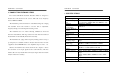
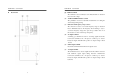
Output terminal
X Output:
Approx. 1Vrms at full scale in measuring input level
Y Output:
Approx. 500mVrms at full scale in measuring distortion
Factor (total harmonic signal output)
Output impedance
Approx. 600Ω
Power source 100/120/220/240V, 50/60Hz, 25VA, 10Watts
Stability against line
voltage fluctuation:
The indication of line voltage fluctuation is changed to
±10%, within ±0.5% of full scale.
Dimensions 310 (W) × 165(H) × 265(D) mm
Weight Approx. 4.6 kg
Accessories
Test leads GTL-103 × 1
User Manual × 1
Operation Environment
Indoor use
Altitude up to 2000m
Installation category II
Pollution Degree 2
WARNING: To avoid electrical shock, the power cord
protective grounding conductor must be connected to
ground.
CAUTION: To avoid damaging the instrument, don’t use
it in a place where ambient temperature exceeds +50℃.
GAD-201G user manual
4
3. PRECAUTIONS BEFORE OPERATION
Unpacking the instrument
The product has been fully inspected and tested before shipping from the
factory. Upon receiving the instrument, please unpack and inspect it to
check if there is any damage caused during transportation. If any sign of
damage is found, notify the bearer and/or the dealer immediately.
Checking the Line Voltage
The instruments can be applied with any kind of line voltage shown in
the table below. Before connecting the power plug to an AC line outlet,
make sure the voltage selector of the rear panel is set to the correct
position corresponding to the line voltage. It might be damaged the
instrument if connected to the wrong AC line voltage.
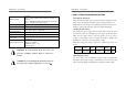
When line voltages are changed, replace the required fuses shown as
below:
Line voltage Range Fuse Line voltage Range Fuse
100V
120V
90-110V
108-132V
T 0.3A
250V
220V
240V
198-242V
216-264V
T0.2A
250V
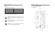
Maximum input voltage
Any input voltage over the maximum specific voltage can damage the
instrument. The specific voltage is determined by how much the peak
value of the input signal is adding plus the superimposed DC voltage.