
User guide

GAD-201G user manual
9
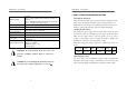
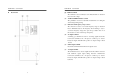
(7) Power switch
Push the switch to left, and the pilot lamps corresponding to the
measuring range will light up to indicate that the distortion meter is
energized and ready for operation.
(8) Measuring range pilot lamps
Pilot lamps corresponding to the scale stage will light up according
to the voltage level and distortion factor of the input signal.
(9) LEVEL zero adjustment
This is for mechanical zero adjustment of Level pointer.
(10) DISTORTION zero adjustment
This is for mechanical zero adjustment of Distortion pointer.
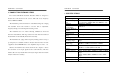
(11) LEVEL meter
The meter is to detect mean values, calibrate sinewave input and
indicate effective values. Its scale stages are 0~1.12, 0~3.5,
-20~+1dB, and -20~+3.2dBm.
(12) DISTORTION meter
The scale stages are 0~1.12%, 0~3.5%, and -20~+1dB.
(13) HIGH pilot lamp (tuning Frequency)
The lamp lights when the center frequency of the basic signal
rejection filter is lower than the basic input frequency.
(14) LOW pilot lamp (TUNING FREQ.)
The lamp lights when the center frequency of the basic signal
rejection filter is higher than the basic input frequency.
GAD-201G user manual
10
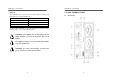
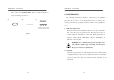
(15) TUNING FREQ. setting knob
The knob is used to adjust the frequency to a desired value.
(16) Power Cord
Connect the power cord to a suitable AC source.
(17) Fuse holder
For circuit protection.
(18) GROUND terminal
The terminal is connected to both the cabinet and signal input
grounding.
(19) L.P.F.(Low Pass Filter) switch
This slide switch can select “Low Pass Filter” function which is at
3dB of 100kHz nominally.