Current Probe and Power Supply USER MANUAL GW INSTEK PART NO.
November 2010 edition This manual contains proprietary information, which is protected by copyright. All rights are reserved. No part of this manual may be photocopied, reproduced or translated to another language without prior written consent of Good Will Corporation. The information in this manual was correct at the time of printing.
TABLE OF CONTENTS Table of Contents SAFETY INSTRUCTIONS .................................. 5 Safety Symbols ....................................................................... 5 PRECAUTIONS ................................................. 7 Preliminary Check ............................................................... 7 OVERVIEW ..................................................... 13 Current Proble Overview ................................................... 13 Features .........................
TABLE OF CONTENTS 4
SAFETY INSTRUCTIONS SAFETY INSTRUCTIONS Safety Symbols This manual contains information and warnings essential for safe operation of the device and for maintaining it in safe operating condition. Before using the device, be sure to carefully read the following safety notes. The symbol printed on the device indicates that the user should refer to a corresponding topic in the manual (marked with the symbol) before using the relevant function.
GCP Series User Manual The following symbols in this manual indicate the relative importance of cautions and warnings. DANGER Indicates that incorrect operation presents an extreme hazard that could result in serious injury or death to the user. Indicates that incorrect operation presents a WARNING significant hazard that could result in serious injury or death to the user. Indicates that incorrect operation presents a CAUTION possibility of injury to the user or damage to the device.
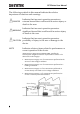
PRECAUTIONS PRECAUTIONS Follow these precautions to ensure safe operation and to obtain the full benefits of the various functions. Preliminary Check Before using the device the first time, verify that it operates normally to ensure that the no damage occurred during storage or shipping. If you find any damage, contact your dealer. • To avoid short circuits and potentially lifethreatening hazards, never attach the GCP-530 or GCP-1030 to a circuit that operates at more than 300V, or over bare conductors.
GCP Series User Manual Un-insulated (core and shield case) • Be careful to avoid damaging the insulation surface while taking measurements. • This instrument is made for use with the GCP206P or GCP-425P POWER SUPPLY. It is possible to use a power supply other than the GCP-206P or GCP-425P, provided that the connector and pin assignments match, and that voltage and other electrical specifications are satisfied.
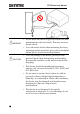
PRECAUTIONS 2. If basic insulation requirements cannot be met between the terminal to which this device is connected and other terminals of the measuring instrument, make sure that the voltage input to the measurement terminal does not exceed the safe voltage level (SELV- E). 3. Read and observe all warnings and precautions relating to electrical safety for the measuring instrument being connected to the probe. Refer to the following standards regarding the meanings of underlined terms.
GCP Series User Manual • Do not allow the device to get wet, and do not take measurements with wet hands. This may cause an electric shock. • To avoid electric shock when measuring live lines, wear appropriate protective gear, such as insulated rubber gloves, boots and a safety helmet. • To avoid damage to the device, protect it from physical shock when transporting and handling. Be especially careful to avoid physical shock from dropping.
PRECAUTIONS • The sensor head is a precision assembly including a molded component, a ferrite core, and a Hall effect element. It may be damaged if subjected to sudden changes in ambient temperature, or mechanical strain or shock, and therefore great care should be exercised in handling it. • The matching surfaces of the sensor head are precisely ground, and should be treated with care. If these surfaces are scratched, performance may be impaired.
GCP Series User Manual NOTE 12 • Correct measurement may be impossible in the presence of strong magnetic fields, such as near transformers and high-current conductors, or in the presence of strong electromagnetic fields such as near radio transmitters. • When sending the device for repair, carefully to prevent damage in transit. Include cushioning material so the instrument cannot move within the package. Be sure to include details of the problem.
OVERVIEW OVERVIEW Current Proble Overview This device can be directly connected to a BNC input connector of a waveform measuring instrument such as an oscilloscope or recorder, and by clamping on a conductor to be measured, allows the current waveform to be easily captured.
GCP Series User Manual Names of Parts(Current Probe) External view 14
OVERVIEW Parts of the Sensor X Opening lever Operating lever for opening the sensor head. Always use this lever to open the sensor head. Y Sensor head This clamps the conductor being measured, and carries out the actual current measurement. It is a precision assembly including a molded component, a ferrite core, and a Hall effect element. It may be damaged if subjected to sudden changes in ambient temperature, or mechanical strain or shock, and therefore great care should be exercised in handling it.
GCP Series User Manual DANGER NOTE 16 To avoid electric shock, do not touch the portion beyond the protective barrier during use. • The output of this device is terminated internally. Use a high-impedance input to the measuring instrument. With an input impedance of 50Ω, accurate measurement is not possible. • If using BNC-banana plug adapters or similar to connect to input terminals other than BNC connectors, make sure the polarity is correct.
OVERVIEW Names of Parts(Power supply) Front view Power indicator Power supply receptacles GCP-425P Rear View GCP-425P 17
GCP Series User Manual Front view GCP-206P Rear View GCP-206P 18
OVERVIEW Power Supply Receptacle 19
GCP Series User Manual MEASURE PROCEDURE Preparations for Measurement (Current Probe) Procedure CAUTION NOTE 1. Have the GCP-206P or GCP-425P POWER SUPPLY, and oscilloscope or recorder for waveform measurement ready. Before turning on the power, make sure that the voltage of the power supply being used matches the supply voltage indicated on the rear panel of the GCP-206P or GCP-425P The output of this device is terminated internally. Use a high-impedance input to the measuring instrument.
OVERVIEW 4.
GCP Series User Manual Demagnetizing and Zero Adjustment Procedure 1. With the waveform measurement instrument input at ground, adjust the trace to the zero position. 2. Set the input coupling of the waveform measurement instrument to DC. 3. Connect the output connector of the GCP-530 or GCP-1030 to the input connector of the waveform measurement instrument. Turn the collar until it clicks, and check that it is locked securely.
OVERVIEW • Do not demagnetize while the GCP-530 or GCP1030 is clamping a conductor to be measured. Demagnetizing causes current to flow into the conductor, which may damage parts in the circuit to be measured. • Check that the conductor being measured is not clamped when supplying power to the GCP-530 or GCP-1030 for the same reason. Demagnetized waveforms are generated when supplying electric power. 4.
GCP Series User Manual Measurement Procedure (Current Probe) Procedure 1. Check that the system is safe, and that the preparations described in the preceding section have been carried out. 2. Pull the sensor opening lever, so that the sensor head opens. 3. Align the sensor so that the current direction indication corresponds to the direction of current flow through the conductor to be measured, and clamp so that the conductor is in the center of the sensor aperture. 4.
OVERVIEW 5. It is now possible to monitor the current waveform. The output rate of the GCP-530 or GCP is 0.1 V/A. The current sensitivity can be derived from the voltage sensitivity of the waveform measurement instrument. For example, if the voltage sensitivity is 10mV/division, the current sensitivity is 100mA/division. NOTE Fig. 1 • When using the GCP-530 or GCP-1030, note that two current probes may not be used simultaneously with the GCP-425P POWER SUPPLY, depending on the current to be measured.
GCP Series User Manual • The maximum continuous input range is based on heat that is internally generated during measurement. Never input current in excess of this level. Exceeding the rated level may result in damage to the probe. • The maximum continuous input range varies according to the frequency of the current being measured. See the figures 3 on page 37 . • If excess current is input, generated heat activates a built-in safety function that blocks normal output.
OVERVIEW NOTE • Do not place any unclamped conductor with an electric current of a frequency of 10 kHz or more near the sensor head. Current flowing in the conductor nearby may heat up the sensor head and cause its temperature to rise, leading to damage to the sensor.
GCP Series User Manual 28 • Depending on the measured current frequency, however some sound may be produced by resonance, it has no effect on measurements. • When performing continuous measurements, it is necessary to be aware that the offset voltage drifts, depending on factors such as the ambient temperature. • Under certain circumstances, oscillation may occur if the probe is connected to the GCP-206P or GCP-425P POWER SUPPLY while the power supply is on. This does not indicate a malfunction.
OVERVIEW • At high frequencies, common mode noise may affect measurements taken on the high voltage side of circuits. If this occurs, reduce the frequency range of the waveform measuring instrument, or clamp onto the low voltage side of the circuit, as appropriate.
GCP Series User Manual Preparations (Power supply) Procedure 1. Turn the power switch off and connect the power cord. To ensure safety, connect the power cord to a properly grounded outlet. 2. Connect the power plug of the sensor to be used to the power receptacle of the GCP-206 or GCP425P. 3. Turn the GCP-206 or GCP-425P power switch on, and check that the front panel power indicator lights.
OVERVIEW Measurement Procedure (Power supply) NOTE • Make sure the sum of the current consumption of the connected current probe(s) does not exceed the rated output current of the GCP-425P (See Fig.1) on page 25. • When using the GCP-425P with Model GCP-530 or GCP-1030 Current Probe, in general only one current probe may be connected. However, depending on the current level of the object under test, two current probes may be connected simultaneously.
GCP Series User Manual APPENDIX The power supply fuse for the GCP-425P, and the power supply voltage selector, are housed in the power input socket on the rear panel. Fuse Replacement (for GCP-206P only) Procedure 1. Turn the power switch off, and then disconnect the power cord. 2. Using a flat screwdriver, pry the catch which holds the fuse holder into the power input socket as shown in the figure, and then remove the fuse holder.
APPENDIX 3. Remove the fuse on the fuse holder and replace with a new one of the same rating and specification. 4. Insert the fuse holder back into the power input socket to finish the replacement of fuse.
GCP Series User Manual Change the power supply voltage setting Procedure 1. Repeat steps 1-2 in the “Fuse replacement” section on page 32. 2. Remove the voltage selector from the fuse holder, rotate it to the desired supply voltage value and then insert back into the fuse holder. The voltage vaule will appear in the voltage window. Check the setting value again. 3. Insert the fuse holder back into the power input socket to finish setting the supply voltage setting.
APPENDIX Current Probe Specifications Accuracy is guaranteed at 23°C~+5°C (72°F±9°F) after the power has been on for 30 minutes. Model-specific specifications Rise time Maximum rated power Weight Accessories Fig. 2A Frequency characteristics (Typical characteristics) GCP-530 DC to 50 MHz (-3 dB) (Characteristics shown in Fig. 2A) 7 ns or less 5.6 VA GCP-1030 DC to 100 MHz (-3 dB) (Characteristics shown in Fig. 2B) 3.5 ns or less 5.3 VA Approx. 230g(8.1oz) Approx. 240g(8.
GCP Series User Manual Common specifications (for GCP-530 and GCP-1030) GCP-530 Operating temperature and humidity range Rated Supply voltage Maximum Peak Current Input Maximum Continuous Input Range Output Voltage Rate Amplitude Accuracy Noise Input Impedance Temperature Coefficient for Sensitivity Storage Temperature and Humidity Range Location for Use Effect of External Magnetic Fields Maximum Rated Voltage Diameter of Measurable Conductors Guaranteed Accuracy Period Cable Lengths 36 GCP-1030 0 to 40
APPENDIX External dimensions Fig.3 Derating according to frequency (For GCP -530) Sensor: Approx. 175(W)×18(H)×40(D)mm Approx. 6.89"(W)×0.71"(H)×1.58"(D)(excluding protrusions) Terminator: Approx. 55(W)×27(H) ×18(D) mm Approx. 2.17"(H) ×1.06"(W)×0.71"(D) 30 20 10 0 10 100 1k 10k 100k 1M 10M 100M Frequency [Hz] Fig.
GCP Series User Manual 10 Inpu t inpedance[Ω] Fig.4 Input impedance (For GCP-530) 1 100m 10m 1m 100 1k 10k 100k 1M 10M Frequency [Hz] Fig.
APPENDIX Power Supply Specifications Model-specific specifications Cable Lengths Sensor cable Approx. 1.5 m (59.0"), Power supply cable Approx. 1 m (39.4") GCP-425P Number of power 4 supply connectors Rated output ±2.5 A (sum total of all current channels) Ripple voltage 50 mVp-p or less Load influence Within output voltage limits indicated above for current output in the range 0 to ±2.
GCP Series User Manual Rated supply frequency 50/60 Hz Common specifications (for GCP-206P and GCP-425P) Compatible sensors Output voltage Temperature influence Operating temperature and humidity range Storage temperature and humidity range Location for use Standards applying 40 GCP-530, GCP-1030 Current Probe 12 V 0.