
Manual


DUAL DISPLAY DIGITAL MULTIMETER
USER MANUAL
12
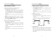
z Figure 4-1 Front Panel
z Figure 4-2 Rear Panel
DUAL DISPLAY DIGITAL MULTIMETER
USER MANUAL
13
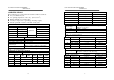
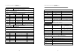
4-6 Input overload protection
The maximum allowable input is shown as table 4-1. Please proceed
the measurement accordingly.
Table 4-1:
FUNCTION RANGE MAXIMUN INPUT
DCV 5V~1000V
1000Vdc or peak ac
ACV (AC+DC) 5V~1000V 1000V rms continuous &
10
7
V•Hz maximum
DCA,ACA(AC+DC)
500μA~2A
fuse protected: 2A 250V
DC,AC20A(AC+DC) 20A no fuse protected
DC,ACmV (AC+DC) 500mV 450V dc or ac peak
OHM all ranges 450V dc or ac peak
CAPACITANCE all ranges 450V dc or ac peak
WARNING: To avoid shock hazard and/or instrument damage,
do not apply input potentials that exceed the input overload
limits shown in table 4-1.
4-7 Input connections to common
WARNING: To avoid shock hazard and/or instrument damage,
do not connect the common input terminal to any source of
more than 500 volts DC or peak AC above earth ground.