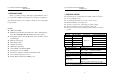
DUAL DISPLAY DIGITAL MULTIMETER USER MANUAL Dual Display Digital Multimeter GDM-8246 This manual contains proprietary information, which is protected by copyrights. All rights are reserved. No part of this manual may be photocopied, reproduced or translated to another language without prior written consent of Good Will company. The information in this manual was correct at the time of printing.
DUAL DISPLAY DIGITAL MULTIMETER USER MANUAL EC Declaration of Conformity We GOOD WILL INSTRUMENT CO., LTD. (1) No.7-1, Jhongsing Rd., Tucheng City, Taipei County 236, Taiwan (2) No.
DUAL DISPLAY DIGITAL MULTIMETER USER MANUAL DUAL DISPLAY DIGITAL MULTIMETER USER MANUAL 1. SAFETY SUMMARY Measuring Circuit Measuring circuits are subjected to working voltage and transient stresses from the circuit to which they are connected during measurement or test. The circuits are divided into the following measurement categories: Measurement category I is for measurements performed on circuits not directly connected to MAINS.
DUAL DISPLAY DIGITAL MULTIMETER USER MANUAL FOR UNITED KINGDOM ONLY NOTE: This lead/appliance must only be wired by competent persons WARNING: THIS APPLIANCE MUST BE EARTHED IMPORTANT: The wires in this lead are coloured in accordance with the following code: Green/ Yellow: Earth Blue: Neutral Brown: Live(Phase) As the colours of the wires in main leads may not correspond with the colours marking identified in your plug/appliance, proceed as follows: DUAL DISPLAY DIGITAL MULTIMETER USER MANUAL The wire
DUAL DISPLAY DIGITAL MULTIMETER USER MANUAL 2. INTRODUCTION DUAL DISPLAY DIGITAL MULTIMETER USER MANUAL 3. SPECIFICATIONS This is a portable, bench-type dual display digital multimeter with a good-performance 50000 counts designed for general purpose application. The dual display allows you to display two functions of the input signal being measured. Features z 50000 counts DMM z Multi-function ACV, DCV, ACA, DCA, R, C , Hz, Continuity Beeper, Diode Test, MAX/MIN, REL, dBm, HOLD, Autohold, Compare.
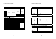
DUAL DISPLAY DIGITAL MULTIMETER USER MANUAL DUAL DISPLAY DIGITAL MULTIMETER USER MANUAL 2. TRUE RMS AC, AC+DC VOLTAGE Accuracy between 2% of range and full range. When the input exceeds the full scale of the selected range, the display will appear “—OL—“ of over-range indication. 4. FREQUENCY MEASUREMENT AT ACV RANGE RANGE 20Hz50Hz 500mV 5V 1%+10 50V 500V 1000V RANGE 500mV 5V 50V 500V 1000V 50Hz2kHz 2kHz10kHz 0.3%+30 0.4%+50 10kHz20kHz 0.
DUAL DISPLAY DIGITAL MULTIMETER USER MANUAL DUAL DISPLAY DIGITAL MULTIMETER USER MANUAL 6. TRUE RMS AC OR AC+DC CURRENT Accuracy Between 2% of range and full range. RANGE 20Hz-45Hz 45Hz-2kHz 2kHz-10kHz 8. RESISTANCE 10kHz-20kHz 500μA 5mA 1%+15 50mA 500mA 1%+15 2%+15 0.5%+15 2A ————————— 20A ————————— Protection Fuse protection 500μA,5mA,50mA,500mA,2A and 20A ranges, 20A range input for 15 seconds max. Crest Factor Range 3.0 at full scale. The burden voltage is the same as the DC current.
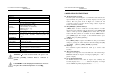
DUAL DISPLAY DIGITAL MULTIMETER USER MANUAL DUAL DISPLAY DIGITAL MULTIMETER USER MANUAL 4. OPERATION INSTRUCTIONS 11. CONTINUITY BEEPER Description Built in buzzer sounds when conductance is less than 5 ohm. Open Voltage 3 volts maximum. Protection 450V dc or peak ac continuous. 12. ENVIRONMENTAL Indoor use, altitude up to 2000m. Ambient Temperature 0℃ to 50℃. Operation Relative Humidity 75% (Maximum). Environment Installation category II Pollution Degree 2 -10℃ to 70℃.
DUAL DISPLAY DIGITAL MULTIMETER USER MANUAL DUAL DISPLAY DIGITAL MULTIMETER USER MANUAL 4-7. Interface Operation This instrument equips RS-232 as standard device with a D-SUB 9 PIN SHELL on the rear panel. Besides, the instrument also provides a GPIB option device with a 24 PIN SHELL in blue. The configuration is compliance with IEE488. For further detailed operation, please refer to the Interface manual. 4-8. Input overload protection The maximum allowable input is shown as table 4-1.
DUAL DISPLAY DIGITAL MULTIMETER USER MANUAL DUAL DISPLAY DIGITAL MULTIMETER USER MANUAL 5. MEASUREMENT TUTORIAL 5-3. Resistance, capacitance, continuity beeper measurements 1). Press the button to select function. 2). Press [▲]or[▼]to the desired range. Press [AUTO/MAN] button 5-1. Voltage measurements (DCV, ACV, DCmV, ACmV) 1).Press the button to select desired function. 2).
DUAL DISPLAY DIGITAL MULTIMETER USER MANUAL DUAL DISPLAY DIGITAL MULTIMETER USER MANUAL For example, if [dBm] is pressed when measuring voltage in the max mode, the maximum value is converted to dBm. To release the dBm function, press [dBm] again. The dBm mode, AC+Hz mode and Compare are not selected concurrently. The reference impedance can be set to any of 21 reference impedances listed in the Table 5-1 according to the steps as follows: 1) Press [SHIFT] [SET] in sequence into SET mode.
DUAL DISPLAY DIGITAL MULTIMETER USER MANUAL DUAL DISPLAY DIGITAL MULTIMETER USER MANUAL 5-10. HOLD and AUTO HOLD measurements The HOLD mode can keep the measured value on the primary display. Press [HOLD] button, the last reading is held on the display in all function. To release the HOLD function, just press [HOLD] again.
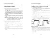
DUAL DISPLAY DIGITAL MULTIMETER USER MANUAL DUAL DISPLAY DIGITAL MULTIMETER USER MANUAL 6. MEASUREMENT TECHNIQUES z Figure 6-1: Voltage Conversion 6-1. dBm measurement technique dBm is defined as above or below a 1mW reference. A voltage measurement is converted to dBm using the following formula: dBm=10*log 10 (1000*voltage value2/reference impedance.) The reference impedance can be set. For example, the reference impedance of 600Ω, 0.7746V will be convert to 0 dBm. 6-2.
DUAL DISPLAY DIGITAL MULTIMETER USER MANUAL DUAL DISPLAY DIGITAL MULTIMETER USER MANUAL z Figure 6-2: Crest Factor 6-3. AC+DC measurement A signal includes an ac component and a dc level. The relationship between the total rms value of the signal and the ac component and the dc component is: rms total= ( ac component rms) 2 + (dc component) 2 6-4. Crest factor Crest factor is often overlooked in determining the accuracy of an ac measurement.
DUAL DISPLAY DIGITAL MULTIMETER USER MANUAL DUAL DISPLAY DIGITAL MULTIMETER USER MANUAL 7. MAINTENANCE 7-3. Line voltage conversion The primary winding of the power transformer is tapped to permit operation from 100/120V, or 220/230V AC 50/60Hz line voltage. Conversion from one line voltage to another is done by changing the line voltage selector switch as shown in Figure 4-2. The rear panel identifies the line voltage to which the unit was factory set.