
User Manual Owner manual


DUAL DISPLAY DIGITAL MULTIMETER
USER MANUAL
13
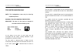
4-7. Interface Operation
This instrument equips RS-232 as standard device with a D-SUB 9 PIN
SHELL on the rear panel. Besides, the instrument also provides a GPIB
option device with a 24 PIN SHELL in blue. The configuration is
compliance with IEE488.
For further detailed operation, please refer to the Interface manual.
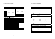
4-8. Input overload protection
The maximum allowable input is shown as table 4-1. Please proceed
the measurement accordingly.
Table 4-1:
FUNCTION RANGE MAXIMUN INPUT
DCV 5V~1000V 1000Vdc or peak ac
ACV (AC+DC) 5V~1000V 1000V rms continuous &
10
7
V•Hz maximum
DCA,ACA(AC+DC) 500μA~2A fuse protected: T2A 250V 1.5kA
breaking capacity
DC,AC20A(AC+DC) 20A fuse protected: F20A 600V
100kA breaking capacity
DC,ACmV (AC+DC) 500mV 450V dc or ac peak
OHM all ranges 450V dc or ac peak
CAPACITANCE all ranges 450V dc or ac peak
RIPPLE all ranges 450V dc or ac peak
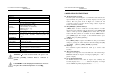
WARNING: To avoid shock hazard and/or instrument
damage, do not apply input potentials that exceed the input
overload limits shown in table 4-1.
4-9. Input connections to common
WARNING: To avoid shock hazard and/or instrument
damage, do not connect the common input terminal to any
source of more than 500 volts DC or peak AC above earth
ground.
DUAL DISPLAY DIGITAL MULTIMETER
USER MANUAL
14
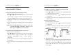
z Figure 4-1 Front Panel
z Figure 4-2 Rear Panel