Logic Analyzer Option DS2-8LA and DS2-16A QUICK START GUIDE GW INSTEK PART NO.
This manual contains proprietary information, which is protected by copyright. All rights are reserved. No part of this manual may be photocopied, reproduced or translated to another language without prior written consent of Good Will Corporation. The information in this manual was correct at the time of printing. However, Good Will continues to improve its products and therefore reserves the right to change the specifications, equipment, and maintenance procedures at any time without notice.
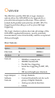
OVERVIEW The DS2-8LA and the DS2-16LA Logic Analyzer options allow the GDS-2000A to be upgraded to a powerful mixed signal oscilloscope. These options include both parallel and serial bus (UART, SPI, I 2C) triggering and decoding as well as powerful logic triggering. The Logic Analyzer options also take advantage of the GDS-2000’s segmented memory, search, automatic measurements, cursor functionality and the exceptional 2M record length.
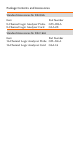
Package Contents and Accessories Standard Accessories for DS2-8LA Item 8-Channel Logic Analyzer Probe 8-Channel Logic Analyzer Card Part Number GTL-08LA GLA-08 Standard Accessories for DS2-16LA Item Part Number 16-Channel Logic Analyzer Probe GTL-16LA 16-Channel Logic Analyzer Card GLA-16
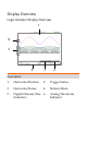
Display Overview Logic Analyzer Display Overview 1 6 5 4 3 2 Description 1. Horizontal Position 2. Trigger Status 3. Horizontal Status 4. Bottom Menu 5. Digital Channel/Bus 6.
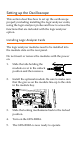
Bus Display Overview 4 1 2 3 9 8 7 6 5 Description 1. Bus Data 2. Start Bit 3. Stop Bit 4. Horizontal Position 5. Trigger Status 6. Horizontal Status 7. Bottom Menu 8. 9.
Setting up the Oscilloscope This section describes how to set up the oscilloscope properly including installing the logic analyzer cards, using the logic analyzer probes and how to access the functions that are included with the logic analyzer option. Installing Logic Analyzer Cards The logic analyzer modules need to be installed into the module slots on the rear panel. Do not insert or remove the modules with the power on. 1. Slide the tabs holding the module cover to the unlock position and then remove.
Using the Logic Analyzer Probes This section will describe how to connect the digital channels to the device under test. To use the digital channels the optional logic analyzer module must be installed. 1. Turn the DUT off to protect it from being short circuited when the probes are attached. 2. Insert the Logic Analyzer probe into the Logic Analyzer input. 3. Connect the ground lead (black) from the logic analyzer probe to the circuit ground on the DUT. GND 4.
Accessing the Logic Analyzer Menu The Logic Analyzer menu can be accessed using the Option key. Option 1. Press the key and select Logic Analyzer to access the Logic Analyzer menu. 2. Press the D15~D0 On/Off soft-key to activate the digital channels. 3. 4. 5. The position of each channel can be set in this menu. Channels can be grouped in this menu. Press Thresholds to set the thresholds. Thresholds can be individually set for every 4 digital channels. I.e., D0~D3, D4~D7 and so on.
Using the Bus Key The Bus key configures the UART, SPI, I2C or Parallel buses. BUS 1. B Press the key to access the Bus menu and to display the bus on the display. Only those digital channels that have been activated from the Logic Analyzer menu will be accessible from the Bus menu. Pressing the Bus key again will remove the bus from the display. UART Bus The UART bus menu is designed to decode RS-232 and other common RS-232 variants such as RS-422 and RS485. 1.
6. Press Event Table to view or save the decoded data in a list. 7. Press Edit Labels to create an on-screen label for the bus. I2C Bus The I2C bus is a 2 wire interface with a serial data line (SDA) and serial clock line (SCLK). The I2C protocol supports 7 or 10 bit addressing and multiple masters. 1. Press the Bus soft-key and select I2C. 2. Press Define Inputs to select the SCLK and SDA inputs. 3. Press Thresholds to set the thresholds.
SPI Bus The serial peripheral interface (SPI) is a full duplex 4 wire synchronous serial interface. The word size is configurable from 4 to 32 bits. The SPI bus triggers on the data pattern at the start of each framing period. 1. Press the Bus soft-key and select SPI. 2. Press Define Inputs to select the SCLK, SS, MOSI and MISO inputs. 3. Press Thresholds to set the thresholds. There are 5 pre-set threshold levels in addition to the User-defined threshold setting (TTL, 5.0V CMOS, 3.3V CMOS, 2.
Parallel Bus The digital channels can be configured as a parallel bus. The number of bits that define the bus as well as which bit is used as the bus clock can also be configured. 1. Press the Bus soft-key and select Parallel. 2. Press Define Inputs to select the number of bits to use in the parallel bus, which digital channels are set to which bits in the parallel bus and which bit, if any, is used for a clock signal. 3. Press Thresholds to set the thresholds.
Trigger Settings The Logic Analyzer option adds Bus and Logic triggers to the GDS-2000A. Note that the digital channels can also be set as the source for the traditional Edge and Pulse Width triggers, but will not be covered here as the operation is covered in the user manual. Logic Trigger Settings The digital channels can be set up to trigger on specified logic levels and for a specified clock edge. 1. Press the trigger Menu key and select Type > Others > Logic. 2. 3. 4.
addition to the User-defined threshold setting (TTL, 5.0V CMOS, 3.3V CMOS, 2.5V CMOS, ECL, PECL, 0V). Thresholds can be set for each 4 lots of digital channels, i.e., D0~D3, D4~D7 and so on. 5. Press Clock Edge to set the transition for the selected clock edge, if any. 6. Press Mode to select either Auto (untriggered roll) or Normal triggering modes. 7. Press Holdoff to set the hold off time.
Bus Trigger Settings -UART The digital channels can be set up to trigger on UART specific conditions. 1. Configure the Bus key to UART. 2. The UART option needs to be set in the Bus menu first before the UART trigger settings can be configured. Press the trigger Menu key and select Type > Others > Bus. 3. Press Trigger On to set triggering conditions. 4.
Bus Trigger Settings –I2C The digital channels can be set up to trigger on I2C specific conditions. 1. Configure the Bus key to I2C. 2. The I2C option needs to be set in the Bus menu first before the I2C trigger settings can be configured. Press the trigger Menu key and select Type > Others > Bus. 3. Press Trigger On to set triggering conditions. There are 7 I2C triggering conditions: Start, Repeat Start, Stop, Missing Ack, Address, Data, Data/Address. 4.
SPECIFICATIONS Logic Analyzer Sample Rate Bandwidth Record Length Input Channels 500MSa/s 200MHz 2M max /ch 16 Digital (D15 - D0) or 8 Digital (D7~D0) Trigger type Edge, Pattern, Pulse Width, Serial bus (I2C, SPI, UART) Thresholds Quad-D0~D3, D4~D7 . . .