
User manual
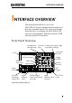
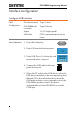
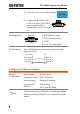
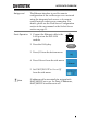
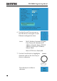
Table Of Contents
- INTERFACE OVERVIEW
- COMMAND OVERVIEW
- COMMAND DETAILS
- Common Commands
- Acquisition Commands
- Autoscale Commands
- Vertical Commands
- Math Commands
- Cursor Commands
- Display Commands
- Hardcopy Commands
- Measure Commands
- Measurement Commands
- Reference Commands
- Run Command
- Stop Command
- Single Command
- Force Command
- Timebase Commands
- Trigger Commands
- System Commands
- Save/Recall Commands
- Ethernet Commands
- Time Commands
- Bus Decode Commands
- Mark Commands
- Search Commands
- Digital Commands
- Label Commands
- Utility Commands
- APPENDX
- INDEX

GDS-2000A Programming Manual
8
7. Press Save Now to save the settings.
8. Connect the RS-232C cable
to the rear panel port: DB-9
male connector. For a
functionality check, see page
13.
Pin Assignment
1
2 345
6789
2: RxD (Receive data)
3: TxD (Transmit data)
5: GND
4, 6 ~ 9: No connection
PC Connection
Use a Null Modem connection as shown in the
diagram below.
GDS-2000A PC
RxDPin2 RxD Pin2
GNDPin5 GND Pin5
TxD Pin3
TxDPin3
Configure the Ethernet Interface
Ethernet
Configuration
MAC Address
Domain Name
Instrument Name
DNS IP Address
User Password
Gateway IP Address
Instrument IP
Address
Subnet Mask
HTTP Port 80 (fixed)
Note
The Ethernet option, DS2-LAN, must first be installed
before proceeding. Please the user manual for further
details.