
User manual
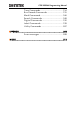
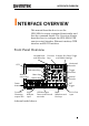
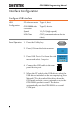

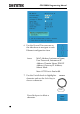
Table Of Contents
- INTERFACE OVERVIEW
- COMMAND OVERVIEW
- COMMAND DETAILS
- Common Commands
- Acquisition Commands
- Autoscale Commands
- Vertical Commands
- Math Commands
- Cursor Commands
- Display Commands
- Hardcopy Commands
- Measure Commands
- Measurement Commands
- Reference Commands
- Run Command
- Stop Command
- Single Command
- Force Command
- Timebase Commands
- Trigger Commands
- System Commands
- Save/Recall Commands
- Ethernet Commands
- Time Commands
- Bus Decode Commands
- Mark Commands
- Search Commands
- Digital Commands
- Label Commands
- Utility Commands
- APPENDX
- INDEX

INTERFACE OVERVIEW
5
INTERFACE OVERVIEW
This manual describes how to use the
GDS-2000A’s remote command functionality and
lists the command details. The Overview chapter
describes how to configure the GDS-2000A USB
remote control interface, Ethernet interface, GPIB
interface and RS-232 interface.
Front Panel Overview
POWER
CH1 CH2
POSITION
TIME/DIV
POSITION
POSITION
VOLTS/DIV VOLTS/DIV
Autoset
Menu
50 %
Force-Trig
Select
TRIGGER
HORIZONTAL
VARIABLE
Measure Cursor
Display Help Save/Recall Utility
Acquire
Single
Run/Stop
Search
Set/Clear
CH3 CH4
POSITION
POSITION
VOLTS/DIV VOLTS/DIV
VERTICAL
M
R
B
Test
CH1 CH2 CH3 CH4 EXT TRIG
CAT
M
W
16pF
300Vpk MAX.
1
CAT
M
W
16pF
300Vpk MAX.
Hardcopy
Option
Menu Off
LEVEL
Zoom
MATH
REF
Demo
Logic Analyzer
1
BUS
Digital Storage Oscilloscope
GDS-2204A
200 MHz 2 GS/s
Visual Persistence Oscilloscope
GEN 1 GEN 2
Default
LCD
Variable knob
and Select key
Autoset, Run/Stop, Single
and Default settings
CH1~CH4
input
Trigger
controls
Function
keys
USB Host port,
Demo and Ground
terminals
Function
Generator
output 1&2
Power
button
Hardcopy key
Option key
Math,
Reference and
Bus keys
Bottom
menu keys
Horizontal
controls
Menu key
Vertical
controls
Logic
Analyzer
input
EXT
trigger
Side menu keys
4 channel model shown.