This manual contains proprietary information, which is protected by copyrights. All rights are reserved. No part of this manual may be photocopied, reproduced or translated to another language without prior written consent of Good Will company. The information in this manual was correct at the time of printing. However, Good Will continues to improve products and reserves the rights to change specification, equipment, and maintenance procedures at any time without notice. Good Will Instrument Co., Ltd. No.
Table of Contents Table of Contents SAFETY INSTRUCTIONS ....................................................5 Safety Symbols ....................................................... 5 Safety Guidelines ................................................... 5 GETTING STARTED ............................................................8 Technical background ............................................. 9 Lineup/Features ....................................................11 Front Panel .........................
SFG-1000 Series User Manual Logic Circuit Test .................................................. 32 Impedance Matching Network Test ....................... 32 Speaker Driver Test............................................... 33 FAQ ................................................................................. 34 APPENDIX ....................................................................... 35 Fuse Replacement ................................................ 35 Specification .........................
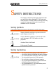
Safety Instructions SAFETY INSTRUCTIONS This chapter contains important safety instructions that you must follow when operating SFG-1000 series and when keeping it in storage. Read the following before any operation to insure your safety and to keep the best condition for SFG-1000 series. Safety Symbols These safety symbols may appear in this manual or on SFG-1000 series. WARNING CAUTION Warning: Identifies conditions or practices that could result in injury or loss of life.
Safety Instructions • • • Storage Environment • • • Pollution degree 1: No pollution or only dry, non-conductive pollution occurs. The pollution has no influence. Pollution degree 2: Normally only non-conductive pollution occurs. Occasionally, however, a temporary conductivity caused by condensation must be expected. Pollution degree 3: Conductive pollution occurs, or dry, non-conductive pollution occurs which becomes conductive due to condensation which is expected.
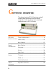
SFG-1000 Series User Manual GETTING STARTED This chapter describes SFG-1000 series in a nutshell, including main features and front/rear/display introduction. Follow the Set Up section to properly install and power up SFG-1000 series. Technical background .............................................9 SFG-1000 series overview Series lineup ........................................................ 11 Main features ....................................................... 11 Panel introduction Main Display ..
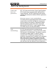
Getting Started Technical background Traditional function generators SFG-1000 series uses the latest Direct Digital Synthesis (DDS) technology to generate stable, high resolution output frequency. The DDS technology solves several problems encountered in traditional function generators, as follows. Constant current circuit methodology This analog function generating method uses a constant current source circuit built with discrete components such as capacitors and resistors.
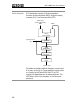
SFG-1000 Series User Manual Block diagram DDS synthesizer consists of Phase accumulator (counter), lookout table data (ROM), Digital-to-analog converter (DAC), and Low-pass filter (LPF). Frequency Control Word (K) 28bit 28bit Phase Accumulator 28bit System Clock (fs) Register Table ROM/RAM 12bit Digital-Analog Converter Low-Pass Filter Output (fo) The phase accumulator adds the frequency control word K at every clock cycle fs. The accumulator output points to a location in the Table ROM/RAM.
Getting Started Lineup/Features Series lineup Features Frequency Offset TTL output −40dB attn.
SFG-1000 Series User Manual Front Panel Main Display 7 segment LED Shows frequency and voltage. TTL indicator Indicates that the TTL output is enabled. For details, see page25. Waveform indicator Indicates the waveform shape: Sine, Square, and Triangle. Frequency indicator Indicates the output frequency: MHz, kHz, or Hz. Voltage indicator (SFG-1013 only) Indicates Voltage unit: mV, or V. For voltage measurement detail, see page22.
Getting Started Entry keys Waveform key Selects the waveform: sine, square, and triangle. For details, see page20. WAVE Activates TTL output. For details, see page25. TTL activation SHIFT WAVE 1 0 Numerical keys Frequency unit selection Cursor selection 9 −40dB attenuation (SFG-1013 only) , 0 SHIFT ) Moves the cursor (frequency editing point) left or right. For details, see page21. SHIFT 4 Specifies the frequency unit: MHz, kHz, or Hz. 8 SHIFT ( Specifies frequency.
SFG-1000 Series User Manual Others Increases (right turn) or decreases (left turn) the frequency. Frequency editing knob Main output OUTPUT 50 Ω TTL output OUTPUT Amplitude control AMPL Outputs sine, square, and triangle waveform. BNC, 50Ω output impedance. For details, see page20. Outputs TTL output waveform, BNC terminal. For TTL mode details, see page25. Sets the sine/square/triangle waveform amplitude. Turn left (decrease) or right (increase).
SFG-1000 Series User Manual Set Up Tilt stand Pull out the handle sideways and rotate it. Place SFG horizontally, Or tilt stand. Place the handle vertically for hand carry.
Getting Started Power up 1. Check the voltage level displayed on the label(1) and make sure it is identical to the AC line. Then connect the power cord(2). 2. Push and turn On the main power switch on the front panel. 3. The display shows the default setup: Sine wave, 1kHz Functionality check 1. Connect SFG main output to measurement device such as oscilloscope. 2. Press the output key. The output is activated and the LED turns On. 3. Observe the output waveform: 1kHz, sine wave.
SFG-1000 Series User Manual Operation Shortcuts Sine wave 250Hz, −40dB amplitude OUTPUT 50 Ω 三 Triangle wave 8kHz,+2V Offset OUTPUT 50 Ω 1. Press Wave key and select Sine 2. Press 2 + 5 + 0 + Shift + 0(Hz) key 3. (SFG-1003) Press Output key, then pull Amplitude knob 4. (SFG-1013) Press Output key, then press Shift + 3 (−40dB) key 1. Press Wave key and select Triangle 2. Press 8 + Shift + 9(kHz) key 3.
Sine/Square/Triangle Wave S INE/SQUARE/TRIANGLE WAVE Select waveform Activate waveform ................................................ 20 Set frequency Enter frequency .................................................... 20 Edit frequency ..................................................... 21 Maximum frequency limit error ............................ 21 Minimum frequency limit error............................. 22 Set amplitude Set Amplitude ......................................................
SFG-1000 Series User Manual Activate waveform Sine / Square / Triangle WAVE 1. Press the wave key repeatedly. The corresponding indicator appears on the display. Sine waveform Square waveform Triangle waveform 2. Press the output key. The LED turns On. OUTPUT 50 Ω 3. The waveform comes out from the main terminal. 10Vp-p (50Ω load) 20Vp-p (no load) Set Frequency Enter frequency Enter the waveform frequency using the numerical keys. 1.
Sine/Square/Triangle Wave Edit frequency SHIFT SHIFT 4 Left cursor key moves the active cursor left. 5 Right cursor key moves the active cursor right. Turn the Frequency knob left to decrease the frequency. Turn the frequency knob right to increase the frequency. Maximum frequency limit error For full error message list, see page37. Sine and square waveform frequency is limited to maximum 3MHz. When the input exceeds it, an error message (Err-1) appears and forces the frequency to 3MHz.
SFG-1000 Series User Manual Minimum frequency limit error For full error message list, see page37. The minimum frequency is 0.1Hz. When the frequency input becomes less than 0.1Hz, an error message (Err-4) appears and forces the frequency to 0.1Hz. Set Amplitude Amplitude setting does not apply to TTL output (page25). Set Amplitude View amplitude (SFG-1013) Attenuate by −40dB SFG-1003 AMPL The range is 2mVpp ~ 10Vpp for 50Ω output impedance.
Sine/Square/Triangle Wave SFG-1013 3 SHIFT Press the Shift key, then 3 (−40dB). The main output is attenuated by −40dB, and the −40dB display indicator in the display turns On. Set Duty Cycle (Square Waveform) The duty cycle setting is not available in sine/triangle waveform. DUTY Pull out the Duty knob. Turn right (left) to increase (decrease) the duty cycle. The default is set at 50%. Enter duty cycle ADJ Range 25% ~ 75% Set Offset Offset setting does not apply to TTL output (page25).
SFG-1000 Series User Manual Limitation Note that the output amplitude, including the offset, is still limited to: −5 ~ +5V (50Ω load) −10 ~ +10V (no load) Therefore excessive offset leads to peak clip as below.
TTL Output TTL OUTPUT Activate TTL Activate TTL ......................................................... 25 Set frequency Enter frequency .................................................... 26 Edit frequency ...................................................... 26 Maximum frequency limit error ............................ 27 Minimum frequency limit error............................. 27 Set duty cycle Enter duty cycle .................................................... 27 Activate TTL 1.
SFG-1000 Series User Manual Set Frequency Enter frequency Enter the waveform frequency using the numerical keys. 1.2MHz 1 2 SHIFT 8 37kHz 3 7 SHIFT 9 4 5 SHIFT 0 45Hz Edit frequency SHIFT SHIFT 4 Left cursor key moves the active cursor left. 5 Right cursor key moves the active cursor right. Turn the Frequency knob left to decrease the frequency. Turn the frequency knob right to increase the frequency.
TTL Output Maximum frequency limit error For full error message list, see page37. Minimum frequency limit error For full error message list, see page37. TTL frequency is limited to maximum 3MHz. When the input exceeds it, an error message (Err-1) appears and forces the frequency to 3MHz. The minimum frequency is 0.1Hz. When the frequency input becomes less than 0.1Hz, an error message (Err-4) appears and forces the frequency to 0.1 Hz. Set Duty Cycle DUTY Enter duty cycle 1. Pull out the Duty knob.
SFG-1000 Series User Manual APPLICATION EXAMPLES Reference Signal for PLL System Description Block diagram The SFG output can be used as a cost-effective reference signal for Phase-Locked-Loop system. Directly connect SFG output to PLL input. SFG series Reference In PLL Output Trouble-Shooting Signal Source Description Block diagram 28 The SFG output can be used as the signal source to test the failed part in a circuit system.
Application Examples Transistor DC Bias Characteristics Test Description Use SFG-1000 series as the signal source for a transistor. Compare the transistor input/output waveform using the oscilloscope. Adjust the DC voltage source to find out the maximum output without distorting the waveform.
SFG-1000 Series User Manual Amplifier Over-Load Characteristic Test Description Block diagram Use the triangle wave output from SFG-1000 series to check the amplifier output distortion caused by overload. The common sine wave is not the ideal source in this case. Observe the linearity of the triangle waveform using an oscilloscope.
Application Examples Test step Transient characteristiclist 1. Apply a triangle waveform to the amplifier first. Adjust the waveform amplitude to make sure there is no clipping. 2. Switch to square waveform and adjust its frequency to the middle of the amplifier pass band, such as 20Hz, 1kHz, and 10kHz. 3. Observe the shape of the amplifier output. The following table shows the possible output distortions and their explanations.
SFG-1000 Series User Manual Logic Circuit Test Description Use the TTL output from SFG-1000 series to test digital circuits. Observe the timing relation of input/output waveform using an oscilloscope. Block diagram Impedance Matching Network Test Description Use SFG-1000 series for impedance matching network: testing its frequency characteristic and matching the impedance. Block diagram Test step 32 Adjust the potentiometer until V2 becomes the half of V1 (V2=0.5V1).
Application Examples Speaker Driver Test Description Use SFG-1000 series for testing the frequency characteristics of audio speakers. Record the volt reading versus the input signal frequency. Oscilloscope (or Voltmeter) Block diagram SFG series Speaker Graph The peak voltage occurs on the resonant frequency of the speaker.
SFG-1000 Series User Manual FAQ ● I pressed the Power switch on the front panel but nothing happens. ● How can I get out of TTL/−40dB mode? ● The device accuracy does not match the specification. ● What are these error messages? I pressed the Power switch on the front panel but nothing happens. Make sure the AC source voltage is set at the rating ±10%, 50/60Hz. For power up sequence, see page17. Otherwise the internal fuse might be blown out. For fuse replacement procedure, see page35.
Appendix APPENDIX Fuse Replacement 1. Take off the Handle In order to detach the handle from the unit, turn the handle down 90 degrees, then pull it off sideways. 220V z 60H 50/ NING W AR AC VE REMO OCK, NING E D SH OP A VOI FORE TO E B UTS INP 7W 1 2. Take off the Cover VA 21 Take off the two metal holdings from the handle joint. Then take the top screw off from the rear panel.
Appendix Error Messages Frequency error Err-1 Err-2 Err-4 Sine, square, and TTL wave frequency over range. This message appears when entering sine / square / TTL waveform frequency larger than 3MHz. The frequency is automatically forced to 3MHz. Triangle wave Frequency over range. This message appears when entering triangle waveform frequency larger than 1MHz. The frequency is automatically forced to 1MHz. Frequency over resolution. This message appears when trying to enter frequency less than 0.1Hz.
Appendix Declaration of Conformity We GOOD WILL INSTRUMENT CO., LTD. (1) No.7-1, Jhongsing Rd., Tucheng City, Taipei County, Taiwan (2) No.
SFG-1000 Series User Manual INDEX 4 summary ...............................................37 F 40dB attenuation faq ........................................................ 34 FAQ ..........................................................34 step....................................................... 22 feature list..................................................11 A frequency editing sine/square/triangle ..............................20 amplifier application example....................
Appendix operation shortcut ......................................18 P storage environment safety instruction..................................... 7 specification .......................................... 38 peak clip ....................................................24 T PLL example application ...........................28 power supply table of contents .......................................... 3 safety instruction .................................... 6 tilt stand ...............................